
Carbon fiber composite rotary ultrasonic milling and grinding device and method

A composite material and rotary ultrasonic technology, which is applied in the field of carbon fiber composite material rotary ultrasonic milling and grinding, can solve the problems of blockage of grinding wheel holes, poor thermal conductivity, and inability to carry out liquid cooling, and achieve the effect of ensuring machining accuracy.

Inactive Publication Date: 2015-05-27
DALIAN KANGSAIPU TECH DEV
View PDF0 Cites 27 Cited by
  • Summary
  • Abstract
  • Description
  • Claims
  • Application Information

AI Technical Summary

Problems solved by technology

Different from the processing of metal materials, the reinforcing fiber in the composite material is the main wear factor in the cutting process. The matrix in the composite material mainly transmits the cutting force to the fiber during the cutting process. Due to the high hardness and strength of the carbon fiber composite material, each Anisotropy, poor thermal conductivity, and no liquid cooling, so in the traditional cutting process, there are phenomena such as fiber head exposure, fiber pulling out from the matrix, fiber and matrix debonding, etc., resulting in greater surface roughness of the workpiece, and even the scrapping of the workpiece; and In the cutting process, the cutting heat is difficult to export, so the tool wears seriously, and the tool is often sharpened and replaced; because the chips are in the form of powder, the hole of the grinding wheel is blocked during the grinding process, and the grinding wheel needs to be reconditioned frequently

Method used


Image

  • Carbon fiber composite rotary ultrasonic milling and grinding device and method

Examples


Embodiment Construction

[0021] The present invention will be further described below in conjunction with accompanying drawing.

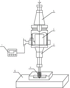
[0022] A carbon fiber composite material rotary ultrasonic milling device, which is composed of an ultrasonic generator 1, an ultrasonic transducer 2, a horn 3, a tool 4, a tool handle 5, and a machine tool body 6;

[0023] The ultrasonic generator 1 is connected with the ultrasonic transducer 2; the ultrasonic transducer 2 is connected with the horn 3; the horn 3 is connected with the cutter 4; the ultrasonic vibration device is connected with the cutter The handle 5 is connected; the ultrasonic vibration device is installed above the machine tool body 6 .

[0024] A carbon fiber composite material rotary ultrasonic milling processing method, comprising the following steps:

[0025] The high-frequency electrical oscillation is generated by the ultrasonic generator and applied to the ultrasonic transducer to convert the high-frequency electrical oscillation into ul...


PUM


Abstract

The invention discloses a carbon fiber composite rotary ultrasonic milling and grinding device and a carbon fiber composite rotary ultrasonic milling and grinding method. The carbon fiber composite rotary ultrasonic milling and grinding device comprises an ultrasonic generator, an ultrasonic transducer, an amplitude transformation pole, a tool, a tool handle and a machine tool body. The carbon fiber composite rotary ultrasonic milling and grinding method is achieved by using ultrasound to assist in milling and grinding so as to process non-ablating carbon / carbon composite materials. According to the carbon fiber composite rotary ultrasonic milling and grinding device and the carbon fiber composite rotary ultrasonic milling and grinding method, frequency of an ultrasonic power source used in the carbon fiber composite rotary ultrasonic milling and grinding method is consistent with inherent frequency of the amplitude transformation pole, and therefore the effect that vibration applied onto the amplitude transformation pole can cause resonance of the amplitude transformation pole is guaranteed; ultrasonic milling and grinding is adopted, and therefore surface quality of a carbon fiber composite work piece is obviously improved, and roughness of the carbon fiber composite work piece is reduced by about 16%-36%; ultrasonic machining is adopted, and therefore stress in the feed direction of a grinding head is reduced by about 44%, and stress in the downward pressing direction of the grinding head is reduced by about 46%; ultrasonic processing temperature rise is reduced by 29% from comparison between ultrasonic milling and grinding temperature and traditional milling and grinding cutting temperature of a carbon fiber composite.

Description

[0001] technical field [0002] The invention relates to a carbon fiber composite material rotary ultrasonic milling processing technology, mainly a device and method for processing carbon fiber composite materials using the ultrasonic milling processing technology. [0003] Background technique [0004] Carbon fiber composite materials have a series of advantages such as light weight, high specific strength, high specific modulus, corrosion resistance, high temperature resistance, etc., and have good compatibility with human muscles, bones, and blood. and other fields have broad application prospects. Different from the processing of metal materials, the reinforcing fiber in the composite material is the main wear factor in the cutting process. The matrix in the composite material mainly transmits the cutting force to the fiber during the cutting process. Due to the high hardness and strength of the carbon fiber composite material, each Anisotropy, poor thermal conductivi...

Claims


Application Information

Patent Timeline
IPC IPC(8): B24B1/04
CPCB24B1/04
Inventor 鞠洪建
Owner DALIAN KANGSAIPU TECH DEV
Learn More