


Quick Research
Generate reliable direction feasibility study reports for your R&D in just a few steps.

Technical Q&A
Discover and master advanced knowledge NOW. Basics, ideas, possibilities, all at once.

Find Solutions
As an expert in R&D theories, this can generate solutions to your technical problems instantly.

Evaluate Feasibility
Analyze your overall solution with one click, know your potential R&D risks in advance.

Monitor Landscape
Get weekly tech updates, stay abreast of the latest tech innovations and key insights.
Heat-convertible heat pipe exchanger and working method thereof
A heat pipe heat exchanger and heat exchanger technology, applied in indirect heat exchangers, lighting and heating equipment, etc., can solve the problems of uncontrollable heat exchange, low heat exchange efficiency, complex structure, etc., and achieve high safety and Flexibility, high heat transfer efficiency, and small size
- Summary
- Abstract
- Description
- Claims
- Application Information
AI Technical Summary
Problems solved by technology
Method used
Image


Examples
Embodiment 1
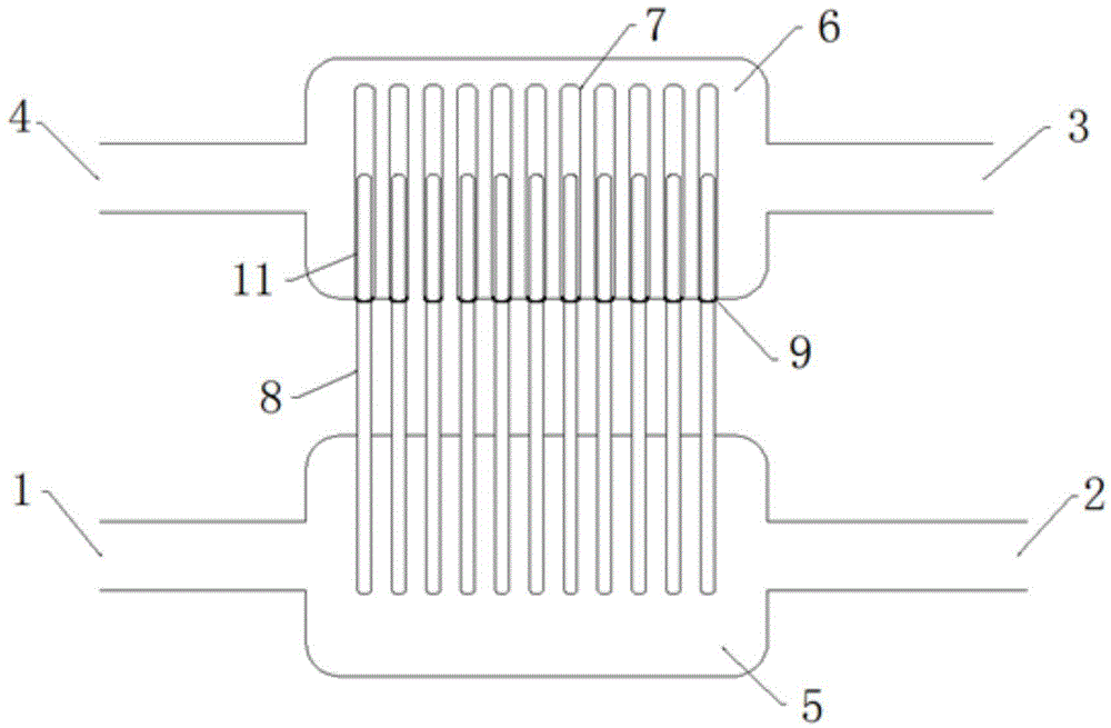
[0035] like figure 1 As shown, a heat pipe heat exchanger capable of transforming heat includes: an air chamber 5 and a liquid collection tank 6; the two ends of the air chamber 5 are respectively provided with an intake pipe 1 and an exhaust pipe 2, and the two ends of the liquid collection tank 6 The liquid inlet pipe 3 and the liquid discharge pipe 4 are respectively provided; the gas chamber 5 and the liquid collection tank 6 are connected by a heat pipe 8, the evaporation section of the heat pipe 8 is inserted into the air 5 chamber, and the condensation section of the heat pipe 8 is inserted into the liquid collection tank 6; the heat pipe 8 , The liquid collection tank 6 or the air chamber 5 can be controlled by the regulating device to move relative to the direction of the heat pipe 8, changing the length of the evaporation section and the condensation section of the heat pipe 8, thereby changing the heat flux density and realizing the control of the heat exchange.
[...
Embodiment 2
[0038] like figure 2 As shown, a heat pipe heat exchanger capable of transforming heat includes: an air chamber 5 and a liquid collection tank 6; the two ends of the air chamber 5 are respectively provided with an intake pipe 1 and an exhaust pipe 2, and the two ends of the liquid collection tank 6 The liquid inlet pipe 3 and the liquid discharge pipe 4 are respectively provided; the gas chamber 5 and the liquid collection tank 6 are connected by a heat pipe 8, the evaporation section of the heat pipe 8 is inserted into the air 5 chamber, and the condensation section of the heat pipe 8 is inserted into the liquid collection tank 6; the heat pipe 8 , The liquid collection tank 6 or the air chamber can be controlled by the regulating device to move relative to the direction of the heat pipe 8, changing the length of the evaporation section and the condensation section of the heat pipe 8, thereby changing the heat flux density and realizing the control of the heat exchange.
[0...
Embodiment 3
[0041] like image 3 As shown, a heat pipe heat exchanger capable of transforming heat includes: an air chamber 5 and a liquid collection tank 6; the two ends of the air chamber 5 are respectively provided with an intake pipe 1 and an exhaust pipe 2, and the two ends of the liquid collection tank 6 The liquid inlet pipe 3 and the liquid discharge pipe 4 are respectively provided; the gas chamber 5 and the liquid collection tank 6 are connected by a heat pipe 8, the evaporation section of the heat pipe 8 is inserted into the air 5 chamber, and the condensation section of the heat pipe 8 is inserted into the liquid collection tank 6; the heat pipe 8 , The liquid collection tank 6 or the air chamber can be controlled by the regulating device to move relative to the direction of the heat pipe 8, changing the length of the evaporation section and the condensation section of the heat pipe 8, thereby changing the heat flux density and realizing the control of the heat exchange.
[00...
PUM
 Abstract
Description
Claims
Application Information
 - R&D Engineer
- R&D Manager
- IP Professional
- Industry Leading Data Capabilities
- Powerful AI technology
- Patent DNA Extraction
Browse by: Latest US Patents, China's latest patents, Technical Efficacy Thesaurus, Application Domain, Technology Topic, Popular Technical Reports.
© 2024 PatSnap. All rights reserved.Legal|Privacy policy|Modern Slavery Act Transparency Statement|Sitemap|About US| Contact US: help@patsnap.com