Gear hobbing tool as well as an insert holder, a chip removal unit, and an insert kit therefor

A technology of inserts and tools, applied to components with teeth, gear cutting tools, gear teeth manufacturing tools, etc., can solve the problems of time-consuming measurement and adjustment, loss of tolerance chain, etc., and achieve the effect of low consumption

Active Publication Date: 2015-05-20
SANDVIK INTELLECTUAL PROPERTY AB
View PDF12 Cites 3 Cited by
  • Summary
  • Abstract
  • Description
  • Claims
  • Application Information

AI Technical Summary

Problems solved by technology

Normally, the replacement of the individual milling inserts does not involve any time-consuming measuring and adjusting operations, but if the accessory fixtures also have to be dismantled and reinstalled, the tolerance chain between the milling inserts and the fixing points of the milling cutter head is broken. lose
In other words, if only for just one chip removal unit, time-consuming measuring and adjustment operations are required

Method used


Image

  • Gear hobbing tool as well as an insert holder, a chip removal unit, and an insert kit therefor
  • Gear hobbing tool as well as an insert holder, a chip removal unit, and an insert kit therefor
  • Gear hobbing tool as well as an insert holder, a chip removal unit, and an insert kit therefor

Examples


Embodiment Construction

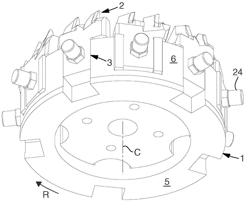
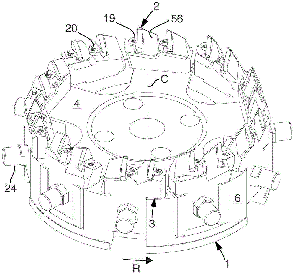
[0043] exist Figure 1-5 In , the construction of a tool according to the invention is shown, the basic parts of which are a milling cutter head (also referred to as “base body”) generally designated 1 and a plurality of replaceable milling inserts generally designated 2 . Each such milling insert is removably mounted in a chip removal unit, generally designated 3 , which in turn is removably mounted in the head 1 . The head 1 is rotatable in the direction R about a central axis denoted C, and the head 1 is obtained by, on the one hand, comprising a pair of generally flat front sides 4 and rear sides 5 parallel to each other and, on the other hand, having a cylindrical Or the outer peripheral surface 6 of a rotationally symmetrical shape, but has a basic shape of a disc or a pulley. In practice, the peripheral surface 6 takes the form of a plurality of partial surfaces which are collectively tangent to an imaginary circle. exist Figure 5 In , RP designates a reference plan...


PUM


Abstract

The invention relates to a tool that is intended for cyclo-palloid gear hobbing and includes a head (1) and a plurality of milling inserts (2) protruding from a front side (4) of the same. The milling inserts are mounted - suitably two by two - in chip removal units (3) that are detachably connected to the head. The individual milling insert (2) is clamped by means of a wedge (19) and a screw (20) easy to access, the wedge (19) acting tangentially against the milling insert behind which there is a robust tangential support in the form of a shoulder (56). By said wedge clamping of the milling insert, there is gained that the milling inserts can be mounted and dismounted in a simple way, as well as that each group of wedge+milling insert+tangential support can be located tangentially and thereby efficiently carry the cutting forces acting on the milling insert. In further aspects, the invention relates in addition to an insert holder as such intended for the tool, a chip removal unit in the form of an insert holder equipped with a milling insert, as well as an insert kit.

Description

technical field [0001] In a first aspect, the invention relates to a gear hobbing tool of the type comprising: in one aspect a head having a front side and a central axis, the head being rotatable about the central axis; and in another aspect In one aspect, a plurality of chip removal units detachably mounted along the front side of the head and each respectively comprising an insert holder having an upper portion and an anchored in the head and a replaceable milling insert The bottom of the milling insert is fixed in a seat located in the upper part of the insert holder and delimited by means of an axial support and a tangential support, more precisely by means of a screw which, in addition to the male thread The exterior includes a keying portion at one end thereof. [0002] In other aspects, the present invention also relates to a blade holder, a chip removal unit and a blade set for knives. [0003] Hobbing tools are particularly suitable for forming beveled teeth in con...

Claims


Application Information

Patent Timeline
IPC IPC(8): B23F21/16
CPCB23F21/223B23C5/006B23C5/22B23F21/226B23F21/236Y10T407/1705Y10T407/1715Y10T407/2206Y10T407/2268Y10T409/105247
Inventor 斯图雷·舍
Owner SANDVIK INTELLECTUAL PROPERTY AB
Why Eureka
Try Eureka