Pneumatic conveying system of fly ash of dust collector

A technology of pneumatic conveying system and dust collector, which is applied in the direction of conveyors, conveying bulk materials, transportation and packaging, etc. It can solve the problems of heavy operation and maintenance workload, low system operation reliability, complex system configuration, etc., and achieve maintenance Small amount, low annual operation and maintenance costs, and low system energy consumption

Inactive Publication Date: 2015-04-22
ZHENJIANG CITY POWER STATION AUXILIARY MACHINERY PLANT
View PDF7 Cites 9 Cited by
  • Summary
  • Abstract
  • Description
  • Claims
  • Application Information

AI Technical Summary

Problems solved by technology

[0003] The number of dust hoppers in the dust collector is usually large. If the traditional single-transmitter pneumatic conveying method is adopted, each transmitter needs to be separately equipped with an inlet valve and a discharge valve. The system configuration is relatively complicat...

Method used


Image

  • Pneumatic conveying system of fly ash of dust collector

Examples


Embodiment Construction

[0026] The present invention will be further described below in conjunction with accompanying drawing.

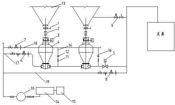
[0027] As shown in the figure, a dust collector fly ash pneumatic conveying system, which includes a conveying device 01, an air source device 02, and a pipeline device 03, and the conveying device 01 is connected to the air source device 02;

[0028] The conveying device 01 is composed of a manual inspection door 1, an expansion joint 2, a feed valve 3, an NPT transmitter 4, a discharge valve 5, an intake valve group 6, an air supply valve group 7, an auxiliary blow valve group 8, a blower Blocking valve group 9; the manual inspection door 1 is located at the bottom of the dust collector hopper 13; the expansion joint 2 is connected to the bottom of the manual inspection door 1, and the NPT transmitter 4 is connected to the bottom of the expansion joint 2 , the top of the NPT transmitter 4 is provided with a feed valve 3, one side of the bottom is connected to a discharge ...


PUM


Abstract

The invention relates to a pneumatic conveying system for fly ash of a dust collector. The system comprises a conveying device, an air source device and a pipeline device; the conveying device is connected with the air source device. According to the pneumatic conveying system of the fly ash of the dust collector, a conveyor mounted below an ash bucket is used for conveying the fly of the dust collector into an ash warehouse; the problems of complex configuration, high conveying energy consumption, serious wear of a pipeline and a valve, and large workload of operation and maintenance of the conveying system of the traditional dust collector can be solved, so that the ash conveying system of the dust collector is economic, practical and reasonable; the operation reliability of the system can also be greatly improved.

Description

technical field [0001] The invention relates to a pneumatic conveying system for powder materials, in particular to a pneumatic conveying system for dust collector fly ash. Background technique [0002] The electric power industry is an important basic industry of the national economy, and also a key industry, a leading industry, and a pillar industry in the national economic development strategy. From the comparison of power production and economic growth in various periods, in the years of continuous economic growth, the growth of power production exceeds the growth of GDP. my country's national conditions of resources determine that my country's energy structure is dominated by thermal power, supplemented by hydropower, supplemented by nuclear power and wind power, and the development of the power structure is very unbalanced. The new coal-fired boilers will generate a large amount of dust-laden flue gas every year. These dust-laden flue gases need to be separated by hig...

Claims


Application Information

Patent Timeline
IPC IPC(8): B65G53/04B65G53/34
Inventor 虞永川卿洪坤虞瑞鹤张凯郑庆喜瞿进李叶凡杨岐
Owner ZHENJIANG CITY POWER STATION AUXILIARY MACHINERY PLANT
Why Eureka
Try Eureka