
Internal-expanding type beveling machine

An internal expansion type beveling machine and core technology, which is applied in the direction of expanding mandrels, metal processing mechanical parts, driving devices, etc., can solve the problem of poor groove roughness and dimensional accuracy, difficulty in tensioning, It is easy to damage the blade and other problems, so as to reduce the tool loss and the frequency of tool replacement, take up less processing space and have a simple device structure.

Active Publication Date: 2015-04-22
苏州博合雅工程材料科技有限公司
View PDF5 Cites 6 Cited by
  • Summary
  • Abstract
  • Description
  • Claims
  • Application Information

AI Technical Summary

Problems solved by technology

The disadvantage of this tensioning mechanism is that the tensioning point inside the pipe can be tightened, but the tensioning point at the pipe mouth is difficult to tighten effectively, which causes the beveling machine to vibrate during work, making the roughness of the groove And the dimensional accuracy is not good, and it is easy to damage the blade

Method used


Image

  • Internal-expanding type beveling machine
  • Internal-expanding type beveling machine
  • Internal-expanding type beveling machine

Examples


Embodiment 1

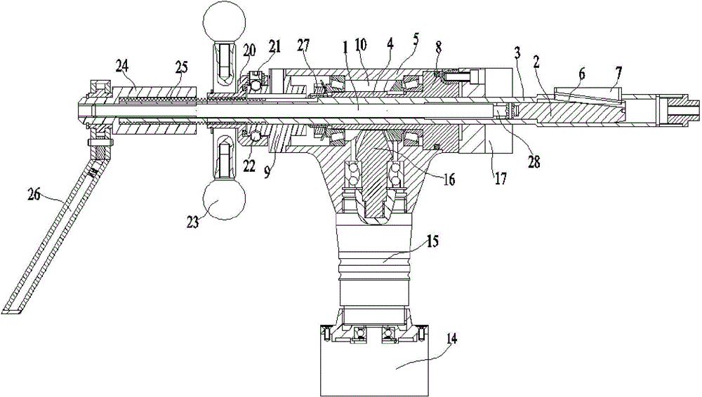
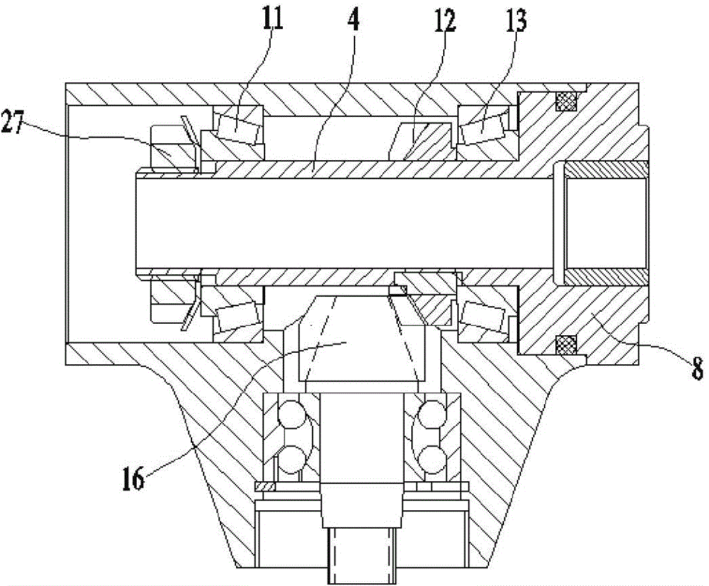
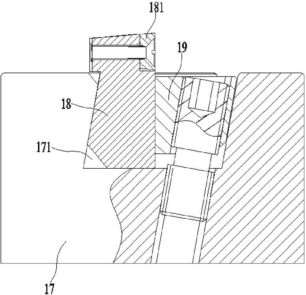
[0022] Embodiment 1: An internal expansion beveling machine, comprising a long inner mandrel 1, a short inner mandrel 2, an outer mandrel sleeve 3, a main shaft sleeve 4 and a housing 5, the long inner mandrel 1, the short inner mandrel The mandrel 2 is embedded in the outer mandrel sleeve 3, the main shaft sleeve 4 is set on the outer surface of the outer mandrel sleeve 3 and is located in the housing 5, the rear outer surface of the outer mandrel sleeve 3 has a trapezoidal thread and wherein, There is a guide groove 31 in the rear part, and at least three oblique guide grooves 6 are provided on the opposite end of the short inner mandrel 2 and the long inner mandrel 1, and an expansion wedge 7 is inserted in the oblique guide groove 6 ;

[0023] The front end of the main shaft sleeve 4 has a cutter base 8, the cutter base 8 is located at the front end of the housing 5, and a rear end cover 9 is mounted on the rear end of the housing 5 to form a cavity 10. A bearing 11, a dr...

Embodiment 2

[0028] Embodiment 2: An internal expansion beveling machine, comprising a long inner mandrel 1, a short inner mandrel 2, an outer mandrel sleeve 3, a main shaft sleeve 4 and a housing 5, the long inner mandrel 1, the short inner mandrel The mandrel 2 is embedded in the outer mandrel sleeve 3, the main shaft sleeve 4 is set on the outer surface of the outer mandrel sleeve 3 and is located in the housing 5, the rear outer surface of the outer mandrel sleeve 3 has a trapezoidal thread and wherein, There is a guide groove 31 in the rear part, and at least three oblique guide grooves 6 are provided on the opposite end of the short inner mandrel 2 and the long inner mandrel 1, and an expansion wedge 7 is inserted in the oblique guide groove 6 ;

[0029] The front end of the main shaft sleeve 4 has a cutter base 8, the cutter base 8 is located at the front end of the housing 5, and a rear end cover 9 is mounted on the rear end of the housing 5 to form a cavity 10. A bearing 11, a dr...


PUM


Abstract

The invention discloses an internal-expanding type beveling machine. The internal-expanding type beveling machine comprises a long inner central spindle, a short inner central spindle, an outer central spindle sleeve, a main shaft sleeve and a shell. The long inner central spindle and the short inner central spindle are embedded into the outer central spindle sleeve, the outer central spindle sleeve is sleeved with the main shaft sleeve located inside the shell, and trapezoid threads are arranged on the external surface of the rear of the outer central spindle sleeve, wherein a guiding groove is formed in the middle and the rear of the outer central spindle sleeve. At least three inclined guiding grooves are formed in the end, backing on to the long inner central spindle, of the short inner central spindle, and an expanding wedged block is inserted into the inclined guiding grooves. A cutter head base is arranged on the front end face of the main shaft sleeve, a tool disc is fixed to the front end face of the cutter head base, a pushing nut is connected with the external surface of the long central spindle sleeve through threads and makes contact with the rear end face of a rear end cover, the rear of the rear end cover is sleeved with the front of the pushing nut, the pushing nut is connected with the rear end cover movably through a groove and balls, and a curved surface handle is fixedly installed at the rear of the pushing nut. Automation of a steel tube punching beveling machine is achieved, and the internal-expanding type beveling machine is simple in structure and convenient to operate, and cuts steel tube inner and outer beveled edges at a time.

Description

technical field [0001] The invention relates to a beveling machine, in particular to an internal expansion beveling machine used for pipeline installation in chemical industry, natural gas, nuclear power, petroleum and other industries. Background technique [0002] At present, the method of steel pipe cutting and beveling machine generally adopts lathe cutting or oxygen cutting and manual grinding wheel grinding. The former is bulky and heavy, and is only suitable for fixed-site processing. For large-diameter steel pipes, it is only suitable for fixed-site processing. , but the surface quality it processes is poor, the efficiency is low, and the metal lattice will change after the processed workpiece is heated. The internal quality of the corresponding material changes, causing the temperature and pressure resistance of the workpiece to decrease. [0003] In the construction of pipes (metal pipes), according to the welding process requirements, the end face of the pipe nee...

Claims


Application Information

Patent Timeline
Patent Type & Authority Applications(China)
IPC IPC(8): B23D79/00B23B31/40B23Q5/10
Inventor 干海娟
Owner 苏州博合雅工程材料科技有限公司
Learn More