
Method for realizing thermal compensation of lead screw of numerical control machine tool

A technology of numerical control machine tools and implementation methods, applied in the directions of digital control, program control, electrical program control, etc., can solve the problems of ball screw thermal compensation accuracy drop, achieve lower accuracy requirements, improve thermal compensation accuracy and stability, reduce The effect of non-linear error

Active Publication Date: 2015-04-01
四川普什宁江机床有限公司
View PDF7 Cites 23 Cited by
  • Summary
  • Abstract
  • Description
  • Claims
  • Application Information

AI Technical Summary

Problems solved by technology

Therefore, using the above method to predict the thermal deformation of the ball screw, there is a certain degree of uncertainty, resulting in a decrease in the accuracy of the thermal compensation of the ball screw

Method used


Image

  • Method for realizing thermal compensation of lead screw of numerical control machine tool
  • Method for realizing thermal compensation of lead screw of numerical control machine tool

Examples


Embodiment 1

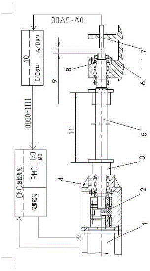
[0034] The invention provides a method for realizing thermal compensation of a lead screw of a numerically controlled machine tool, the steps of which are as follows:

[0035] a. Detect the thermal deformation of the screw of each linear axis of the machine tool, and divide it into several stages from 0 to the maximum deformation;

[0036] b. Divide the lead screw thermal compensation section corresponding to the machine tool coordinates, and set a compensation point for each section;

[0037] c. Detect the positioning accuracy error of each section of the corresponding coordinate axis of the machine tool when the lead screw of each linear axis of the machine tool is thermally deformed at each level;

[0038] d. Establish a thermal compensation database for machine tool screw;

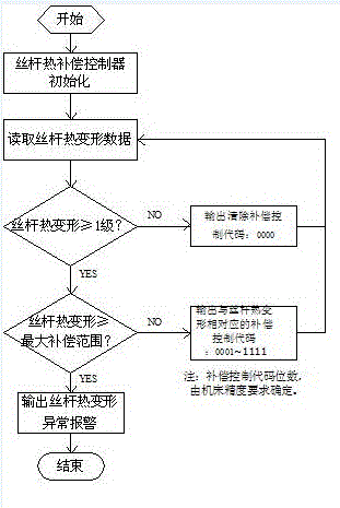
[0039] e. Develop a thermal compensation controller to convert each level of thermal deformation of the lead screw into a corresponding thermal compensation control code;

[0040] f. According to the...

Embodiment 2

[0042]On the basis of embodiment 1, the best implementation mode of the present invention is:

[0043] The thermal deformation of each linear axis screw of the machine tool is detected by using a non-contact displacement sensor (such as: eddy current displacement sensor, capacitive displacement sensor, etc.), on the end surface of the non-motor connection end (floating end) of the machine tool screw , direct real-time detection of the thermal deformation of the lead screws of each linear axis of the machine tool. And the thermal deformation of each linear axis lead screw of the machine tool, from 0 to the maximum value, is divided into several grades according to the accuracy requirements of the machine tool after compensation.

[0044] The division of the lead screw thermal compensation section corresponding to the coordinates of the machine tool is to divide the entire stroke of each linear axis of the machine tool into several sections, and each section corresponds to a com...


PUM


Abstract

The invention discloses a method for realizing thermal compensation of a lead screw of a numerical control machine tool. The method for realizing thermal compensation of the lead screw of the numerical control machine tool comprises the steps of a. detecting thermal deformation of each linear-axis lead screw of the machine tool and dividing the thermal deformation into a plurality of levels according to a stepped manner from zero to the maximum deformation; b. dividing lead screw thermal compensation sections against machine tool coordinates, wherein a compensation point is set for each section; c. detecting the positioning accuracy error of each section of a corresponding coordinate axis of the machine tool when each linear-axis lead screw of the machine tool is thermally deformed at each level; d. establishing a machine tool lead screw thermal compensation database; e. developing a thermal compensation controller and converting treatment of thermal deformation at each level to corresponding thermal compensation control codes; f. acquiring a current compensation amount from the thermal compensation database according to a current compensation control code and a machine tool coordinate position, and conducting real-time dynamic compensation to the thermal deformation of the lead screw. By adopting the method for realizing thermal compensation of the lead screw of the numerical control machine tool, uncertainty factors caused by indirect prediction of lead screw thermal deformation through lead screw temperature change are avoided, and the actual situation of the thermal deformation of the lead screw of the machine tool can be more truly reflected.

Description

technical field [0001] The invention relates to the related technical field of CNC machine tool manufacturing, in particular to a method for realizing automatic detection and compensation of thermal deformation of a lead screw of a CNC machine tool. Background technique [0002] CNC machine tools using semi-closed-loop control are welcomed by the majority of users because of their high cost performance, and have a good market prospect. However, the CNC machine tool with semi-closed loop control has the problem of thermal deformation of the servo shaft screw, which directly affects the machining accuracy and stability of the machine tool. Therefore, as an important means to improve the dynamic accuracy and stability of semi-closed-loop CNC machine tools, automatic compensation technology for thermal deformation of lead screw has been applied more and more, and the realization methods are also diversified. With the development of machine tool manufacturing technology in the d...

Claims


Application Information

Patent Timeline
IPC IPC(8): G05B19/18
CPCG05B19/402
Inventor 曹星际姜华张学智
Owner 四川普什宁江机床有限公司
Learn More