
Steel wire rod or bar steel

A steel wire rod and quality technology, applied in the field of steel wire rod or bar steel, can solve the problem that there is no regulation on the oxidation depth of the grain boundary

Inactive Publication Date: 2015-02-11
NIPPON STEEL CORP
View PDF9 Cites 27 Cited by
  • Summary
  • Abstract
  • Description
  • Claims
  • Application Information

AI Technical Summary

Problems solved by technology

However, it is limited to steel structures that only specify ferrite and cementite, and there is no regulation on the surface roughness and surface grain boundary oxidation depth that have a great influence on cracking in cold forging.

Method used


Image

  • Steel wire rod or bar steel
  • Steel wire rod or bar steel
  • Steel wire rod or bar steel

Examples


Embodiment

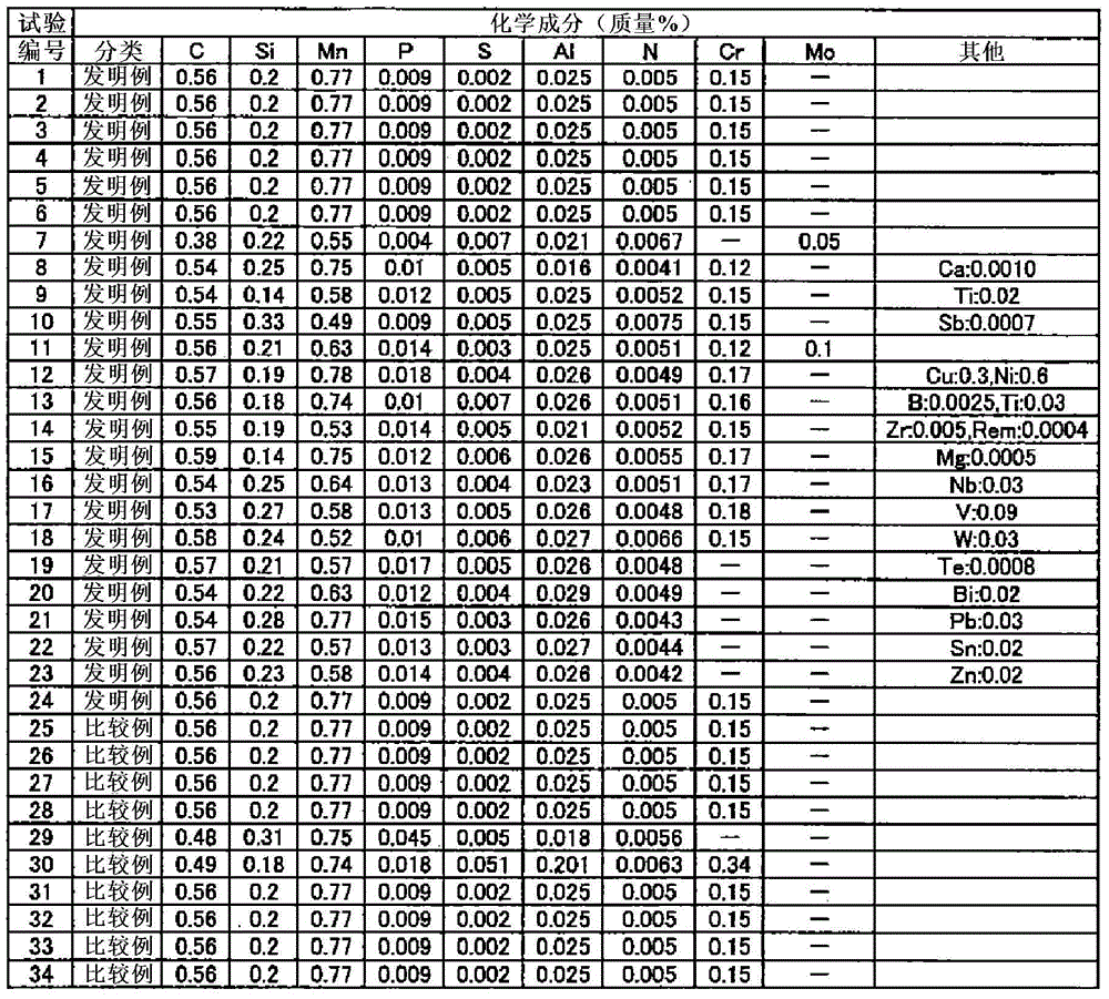
[0136] The present invention is specifically described below by way of examples. Wherein, these examples are used to illustrate the present invention, but not to limit the scope of the present invention.

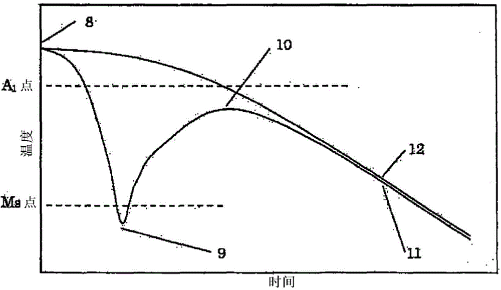
[0137] A 162 mm square billet having the chemical composition shown in Table 1 was rolled into a φ45 mm steel bar according to the conditions in Table 2, and immediately after rolling, it was rapidly cooled, reheated, and then air-cooled. The final rolling temperature, cooling temperature, and reheating temperature were measured with a radiation thermometer. figure 1 The positional relationship of each radiation thermometer, rolling mill, water cooling device, and cooling bed is illustrated, figure 2 Temperature changes are illustrated. That is, as an example of the summary of the rolling line related to the present invention figure 1 As shown, a steel slab heated in a heating furnace 1 is rolled in a hot rolling mill 2 , and the final temperature is measured with a fi...


PUM


Abstract

A steel wire rod or bar steel, the chemical composition of which comprises, in terms of mass%, 0.1-0.6% of C, 0.01-1.5% of Si, 0.05-2.5% of Mn, 0.015-0.3% of Al, and 0.004-0.015% of N, optionally together with definite arbitrary element(s), with the balance consisting of iron and impurities, wherein the impurities contain not more than 0.035% of P and not more than 0.025% of S. In the steel wire rod or bar steel: a surface layer area to a depth equivalent to 15% of the section radius from the surface is a steel tissue that is configured from ferrite having an average particle diameter of 1-15 mum and spherical cementite having an average aspect ratio of 2 or less and an average particle diameter of 0.1-2 mum; an inner area ranging from the point of a depth equivalent to 25% of the section radius from the surface to the core is a steel tissue that is configured from ferrite having an average particle diameter of 15-40 mum and pearlite and / or spherical cementite; after removing surface scale, the surface roughness (Ra) of the surface in the circumferential direction is not more than 4 mum; and the depth of a grain boundary oxidation layer on the surface is not more than 30 mum.

Description

technical field [0001] The present invention relates to steel wire rods or steel bars (including bar in coils; the same applies hereinafter) suitable for cold forging and the like. This application claims the priority based on Japanese Patent Application No. 2012-131316 for which it applied to Japan on June 8, 2012, The content is used here. Background technique [0002] In recent years, in order to increase productivity, it is required to reduce or omit mechanical processing represented by cutting, so the demand for cold forging for medium carbon steel is increasing. However, the deformation resistance of medium carbon steel is higher than that of low carbon steel and low alloy steel, and lacks deformation ability (ductility), so there is a problem that mold cracking and steel material cracking are prone to occur. Therefore, in order to reduce deformation resistance and improve deformability of steel materials for cold forging, spheroidizing annealing for spheroidizing cem...

Claims


Application Information

Patent Timeline
IPC IPC(8): C22C38/00C22C38/06C22C38/60C21D8/06
CPCC21D9/085C21D2211/009C22C38/002C22C38/005C21D2211/005C22C38/04C22C38/22C22C38/60C21D2211/003C22C38/00C22C38/42C22C38/26C22C38/06C22C38/02C21D9/525C21D7/02C22C38/28C22C38/001C21D8/06C22C38/18C22C38/24C22C38/32
Inventor 门田淳宫西庆山崎真吾
Owner NIPPON STEEL CORP
Learn More