A kind of manufacturing method of metal direct plating RFID electronic tag antenna
A production method and electronic label technology, applied in the direction of the structure and form of radiation elements, can solve the problems of environmental pollution and high cost, and achieve the effects of reducing production cost, long production time and simple process
- Summary
- Abstract
- Description
- Claims
- Application Information
AI Technical Summary
Problems solved by technology
Method used
Image
Examples
Embodiment 1
[0044] This embodiment provides an RFID film aluminum antenna, which is obtained through the following steps:
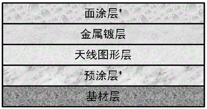
[0045] The substrate layer is PET film with a thickness of 20 μm; the shape and size of the antenna are designed according to the specific application requirements; according to the designed antenna pattern, laser engraving is made on the flexible printing plate to make a printing plate roll engraved with the antenna pattern; In the cavity of the vacuum coating machine, the direct coating oil (mineral oil, German Leybold LVO108) is transferred to the printing plate roller through the anilox roller (the number of lines is 180); the substrate rolls over the surface of the printing plate roller, and the antenna is transferred Graphics, form the antenna graphic layer, the temperature is 80 ℃, the vacuum condition is 1×10 -2 Pa; coating material is aluminum, vacuum condition 4×10 -3 Pa, metal direct plating is carried out on the PET film that has been partially directl...
Embodiment 2
[0047] This embodiment provides an RFID thin film copper antenna, which is obtained through the following steps:
[0048] The substrate layer is PVC film with a thickness of 30 μm; the shape and size of the antenna are designed according to the specific application requirements; according to the designed antenna pattern, laser engraving is made on the flexible printing plate to make a printing plate roll engraved with the antenna pattern; In the cavity of the vacuum coating machine, the direct coating oil (silicone oil, Dow Corning DC705) is transferred to the printing plate roller through the anilox roller (the number of lines is 200); the substrate rolls over the surface of the printing plate roller, and the antenna pattern is transferred to form Antenna pattern layer, temperature 100 ℃, vacuum condition 1×10 -2 Pa; the coating material is copper, and the vacuum condition is 1×10 -3 Pa, metal direct plating is performed on the PVC film that has been partially directly coa...
Embodiment 3
[0050] This embodiment provides an RFID paper-based silver antenna, which is obtained through the following steps:
[0051] The substrate layer is coated paper 90 g / m 2 ; Pre-coat one side of the coated paper, the pre-coating is polyethylene, the speed is 120m / min, the temperature zone of the drying tunnel is 110-130 ℃, and the dry weight of the coating is 1.3 g / m 2 ; Design the shape and size of the antenna according to the specific application requirements; according to the designed antenna pattern, laser engrave it on the flexible printing plate to make a printing plate roller engraved with the antenna pattern; (The number of lines is 120) Transfer the direct plating oil (perfluoropolyether oil, Fomblin YR-1800) to the printing plate roller; the substrate rolls over the surface of the printing plate roller, transfers the antenna pattern to form the antenna pattern layer, Temperature 120 ℃, vacuum condition 2×10 -1 Pa; coating material is silver, vacuum condition 6×10 -2...
PUM
 Abstract
Description
Claims
Application Information
 - Generate Ideas
- Intellectual Property
- Life Sciences
- Materials
- Tech Scout
- Unparalleled Data Quality
- Higher Quality Content
- 60% Fewer Hallucinations
Browse by: Latest US Patents, China's latest patents, Technical Efficacy Thesaurus, Application Domain, Technology Topic, Popular Technical Reports.
© 2025 PatSnap. All rights reserved.Legal|Privacy policy|Modern Slavery Act Transparency Statement|Sitemap|About US| Contact US: help@patsnap.com


