
Control valve for oil atomizer

A fuel injector and control valve technology, which is used in machines/engines, fuel injection devices, engine components, etc., can solve the problem of increased difficulty in control valve control by electromagnets, insufficient reliability, durability, and high-cost replacement and maintenance. Cost and other issues, to achieve the effect of shortening the matching length, reducing the quality and reducing the manufacturing cost

Active Publication Date: 2015-01-07
CHINA FAW LIMITED WUXI FUEL INJECTIONEQUIP RES INST +1
View PDF9 Cites 8 Cited by
  • Summary
  • Abstract
  • Description
  • Claims
  • Application Information

AI Technical Summary

Problems solved by technology

Moreover, it is more difficult for the electromagnet to control the control valve, the opening delay of fuel injection is increased, the stroke of the control valve is difficult to control, the precision of fuel injection is reduced, and the ability of multiple injections is reduced
[0003] In recent years, many companies have adopted pressure-balanced control valves, such as the slide valve structure of Delphi Company. Balanced, but the armature guide rod of this structure has high processing and manufacturing costs, and with the accumulation of service time, it will bring high cost replacement and maintenance costs due to wear; the line-sealed cone valve structure of Bosch Company (US 7870847 B2 , CN 101535625A), the armature is used to seal the control valve seat, and a hydraulic balance control chamber is constructed with the guide rod. Similarly, due to the limitations of the cone valve structure itself, there are great deficiencies in reliability and durability

Method used


Image

  • Control valve for oil atomizer
  • Control valve for oil atomizer
  • Control valve for oil atomizer

Examples


Embodiment 1

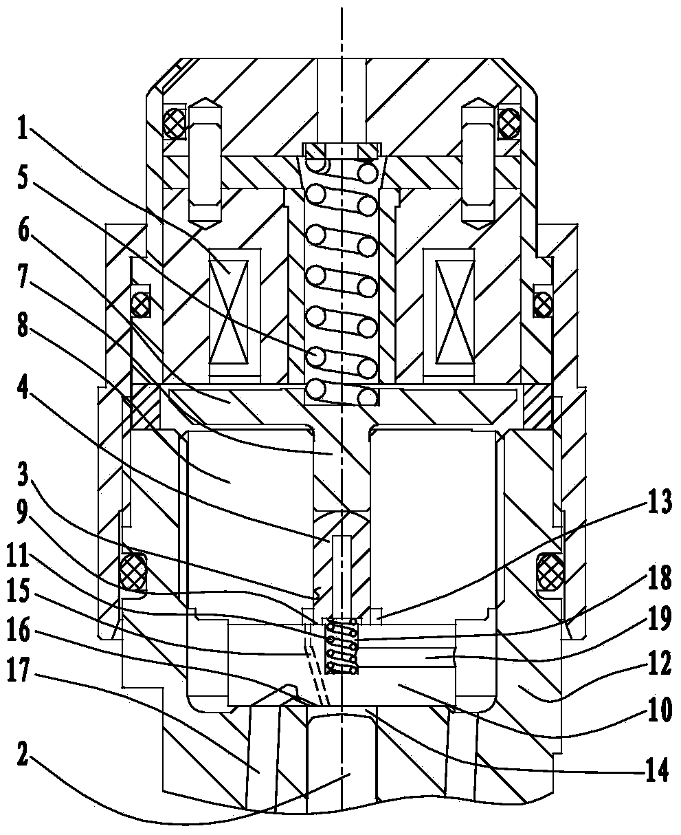
[0025] Such as figure 1 As shown, the control valve for the fuel injector of embodiment 1 is mainly composed of an electromagnet 1, a sealing pin 4, an electromagnet spring 5, an armature 6, an armature guide rod 7, a control valve seat 8, a throttle orifice 10, The auxiliary spring 11 is composed of the injector body 12; the electromagnet 1 is connected to the upper end of the injector body 12, and the electromagnet spring 5 in the electromagnet 1 presses down on the armature 6; the control valve seat 8 is installed on the injector In the concave cavity on the upper part of the body 12, the center of the control valve seat 8 is provided with a control valve seat inner hole 3, and the armature guide rod 7 is placed in the control valve seat inner hole 3 and can move axially; the throttle orifice 10 is arranged on the control valve seat. Below the seat 8, the fuel inlet passage 16 on the throttle orifice 10 communicates with the fuel inlet passage 17 on the injector body 12; t...

Embodiment 2

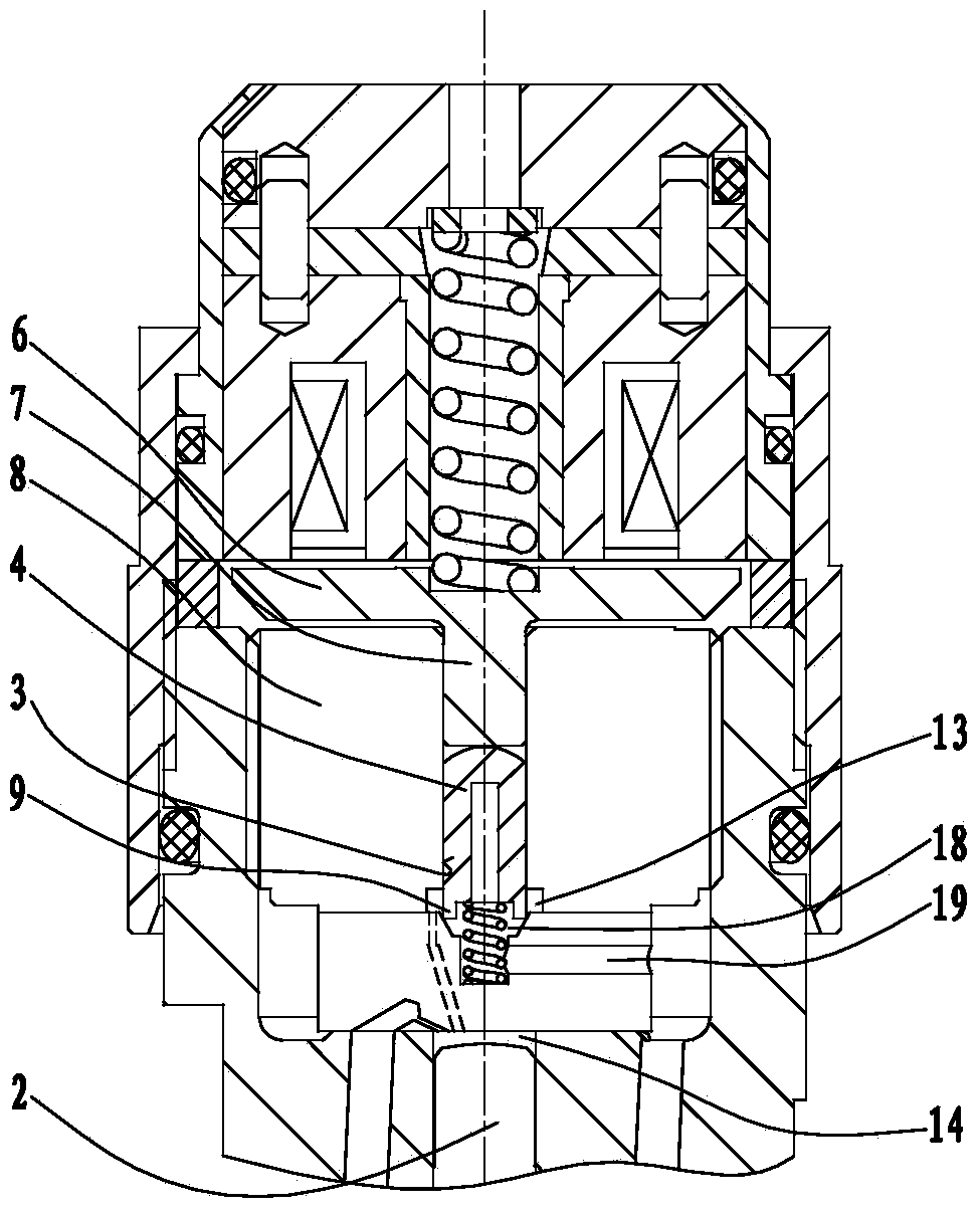
[0029] Such as figure 2 As shown, the difference between the control valve in embodiment 2 and the control valve in embodiment 1 lies in the structure of the support surface at the upper end of the throttle orifice 10 and the support surface at the lower end of the closing part 9 .

[0030] exist figure 1 In the shown embodiment, the support surface at the upper end of the throttle orifice 10 is a conical concave surface, the support surface at the lower end of the closing part 9 is a high-precision plane or conical surface, and the high-precision plane or conical surface is in contact with the sealing pin 4 The outer circular surfaces of the two meet to form a circular intersecting line, and the circular intersecting line presses down on the conical concave surface of the throttle orifice 10 to form a high-pressure sealing fit.

[0031] In order to make the leakage of high-pressure fuel in the valve chamber 13 small, the pressure of the closing part 9 on the conical concav...

Embodiment 3

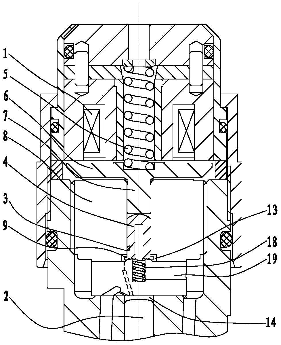
[0033] Such as image 3 As shown, the difference between the control valve in Embodiment 3 and the control valve in Embodiment 1 lies in the structure of the upper support surface of the throttle orifice 10 and the lower support surface of the closing part 9 .

[0034] exist image 3 In the shown embodiment, the support surface at the upper end of the throttle orifice 10 is a high-precision spherical convex surface, the closing part 9 is an annular platform formed by extending the lower end of the sealing pin 4 outward, and the sealing surface at the lower end of the closing part 9 is Continuing the connection of the plane and the conical surface, the plane and the conical surface meet to form a circular intersecting line, and the circular intersecting line presses down on the spherical convex surface of the throttle orifice 10 to form a high-pressure sealing fit.

[0035] In order to make the leakage of high-pressure fuel in the valve chamber 13 small, the pressure of the cl...


PUM


Abstract

The invention relates to a control valve for an oil atomizer. The control valve comprises electromagnets, a sealing bolt pin, electromagnet springs, an armature, an armature guide rod, control valve bases, a restriction orifice and an oil atomizer body. The control valve is characterized in that the sealing bolt pin is arranged in inner holes of the control valve bases; a high-pressure sealing face is formed by the outer circle surface of the sealing bolt pin and the inner holes of the control valve bases; a valve chamber is defined by the sealing bolt pin, the control valve base and the restriction orifice and is communicated with a control chamber through an oil outlet path; the sealing bolt pin is in rigid connection with the armature guide rod and is pressed on a supporting face at the upper end of the restriction orifice under downward elastic force of the electromagnet springs; a closed portion is arranged on the lower end face of the sealing bolt pin; a high-pressure sealing face is formed by the supporting face of the lower end of the closed portion and the supporting face of the upper end of the restriction orifice; a blind hole is formed in the center of the restriction orifice; an oil returning cavity is formed between the blind hole and the lower end face of the sealing bolt pin and is communicated with an oil returning channel. The control valve can be closed only through small spring pre-tightening force.

Description

technical field [0001] The invention relates to a control valve for a fuel injector, in particular to a pressure-balanced control valve for a fuel injector, which belongs to the field of diesel engine fuel injection systems. Background technique [0002] At present, the commonly used control valve forms of diesel engine injectors in my country mainly include ball valve (US7866575 B2) of Bosch company and planar valve (US2012 / 0012680 A1) of Denso company, both of which are pressure unbalanced control valves. The high-pressure fuel acts on the ball valve or plane valve to generate a certain fuel pressure. In order to close the oil circuit, a spring preload force greater than this fuel pressure and in the opposite direction is required to act on the control valve. In order to open the oil circuit, a more Large electromagnet attraction to overcome this spring force. As the system pressure rises, the fuel pressure acting on the valve rises, the spring preload increases according...

Claims


Application Information

Patent Timeline
Patent Type & Authority Applications(China)
IPC IPC(8): F02M61/10F02M51/06
Inventor 张涛俞建达张建刚蔡珍辉
Owner CHINA FAW LIMITED WUXI FUEL INJECTIONEQUIP RES INST
Learn More