
Local postweld heat treatment method of stub tube fillet joint

A technology for post-weld heat treatment and fillet joints, applied in heat treatment furnaces, heat treatment equipment, heat treatment process control, etc., can solve problems such as joint scrapping and material performance damage

Inactive Publication Date: 2015-01-07
SUZHOU NUCLEAR POWER RES INST +1
View PDF3 Cites 4 Cited by
  • Summary
  • Abstract
  • Description
  • Claims
  • Application Information

AI Technical Summary

Problems solved by technology

When the maximum temperature of the offset exceeds the phase transition temperature of the material, it will cause damage to the material properties, and even directly lead to the scrapping of the joint

Method used


Image

  • Local postweld heat treatment method of stub tube fillet joint
  • Local postweld heat treatment method of stub tube fillet joint
  • Local postweld heat treatment method of stub tube fillet joint

Examples


Embodiment 1

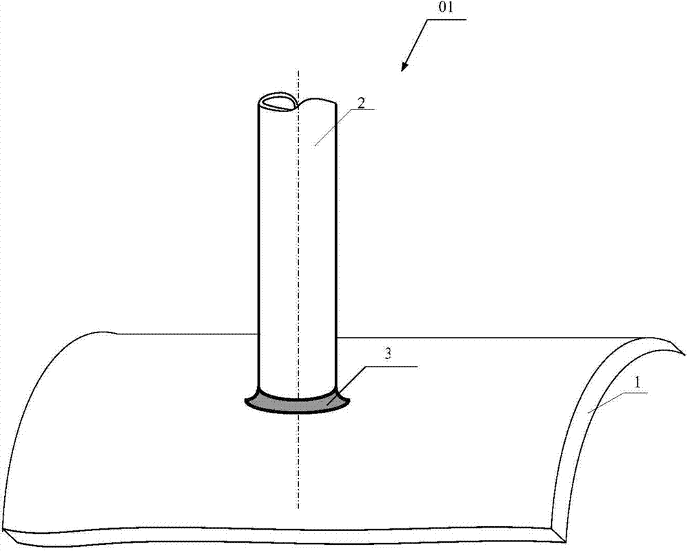
[0076] A pressure vessel cylinder is made of BHW35, with an outer diameter of 1800mm and a wall thickness of 95mm. There is a corner joint on it. The material of the joint seat is 20G, and the specification is OD273×22(mm). The welding repair process requires local post-weld heat treatment for the fillet joint. The constant temperature of the heat treatment is 600°C, the heating and cooling rate is 300°C / h, and the heating width on the cylinder during heat treatment is three times the wall thickness of the cylinder.

[0077] Using the method of the present invention to carry out local post-weld heat treatment on the fillet joint of the connecting pipe seat, the specific implementation steps are as follows:

[0078] (1) Calculation and selection of heating power

[0079] According to the requirements of the post-weld heat treatment process, the minimum power required for heating on the cylinder is calculated to be 17kW. With the center of the nozzle seat as the center, within ...

Embodiment 2

[0091] There is a fillet weld seam on the head of a container that requires local post-weld heat treatment after repair. The material of the head and the connecting pipe is 12Cr1MoVG, the outer diameter of the head is 828mm, and the wall thickness is 82mm; the outer diameter of the connecting seat is 347mm, and the wall thickness is 40mm. The welding process requires post-weld heat treatment for the fillet joint. The post-weld heat treatment process requires a constant temperature of 720°C, a heating and cooling rate of 75°C / h, and a heating width of 164mm that is twice the wall thickness of the head.

[0092] Using the method of the present invention to carry out local post-weld heat treatment on the fillet joint of the connecting pipe seat, the specific implementation steps are as follows:

[0093] (1) Calculation and selection of heating power

[0094] According to the requirements of the post-weld heat treatment process, the minimum power required for heating the head sid...


PUM

PropertyMeasurementUnit
Outer diameteraaaaaaaaaa
Wall thicknessaaaaaaaaaa
Radiusaaaaaaaaaa

Abstract

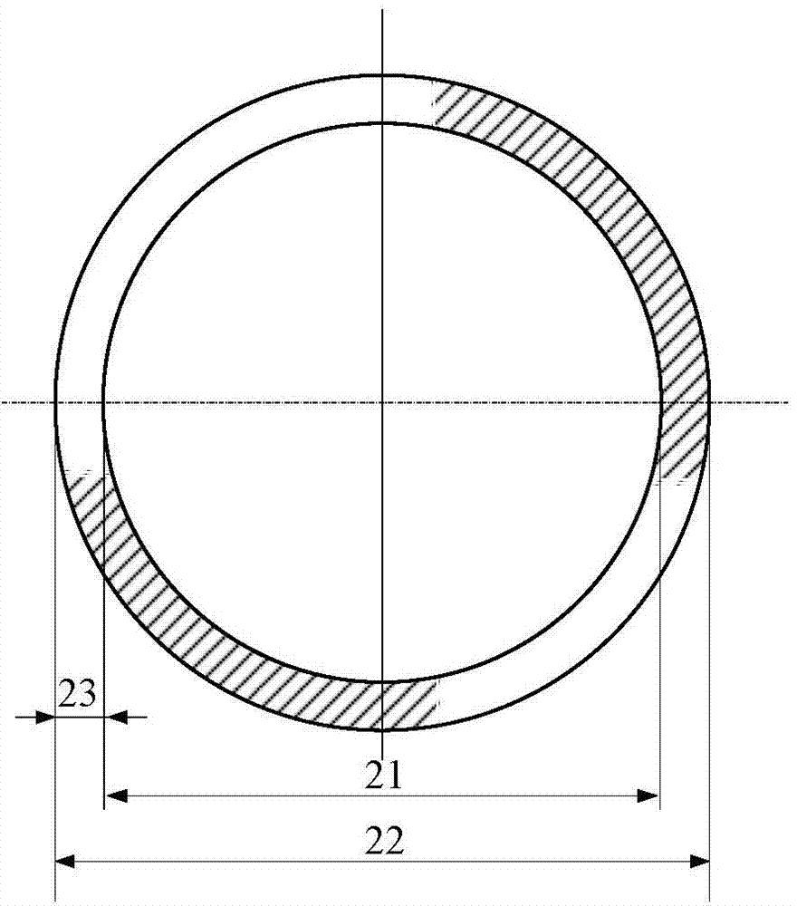
The invention relates to a local postweld heat treatment method of a stub tube fillet joint. The method comprises the following steps of with fillet weld as the center, arranging a heater having power of Q1 on a barrel body and arranging a heater having powder of Q2 on a stub tube, wherein Q1 is calculated according to a preset postweld heat treatment process and a desired heating range and Q2 is calculated according to the formula A. The method can carry out quantitative heating power compensation on a side of the fillet joint having larger heat transfer capacity so that a highest-temperature point in the heating range is located on the fillet weld and thus the highest-temperature point in the heating range does not deviate from the fillet weld, the adverse influence produced by the traditional postweld heat treatment process on joint performances is avoided and postweld heat treatment requirements are satisfied.

Description

technical field [0001] The invention relates to a local post-weld heat treatment method for the fillet joint of the socket, which is especially suitable for the post-weld heat treatment of the fillet joint of the socket whose length is greater than or equal to 5 times the outer diameter of the socket, or the socket has been connected with an external pipeline Post-weld heat treatment of socket fillet joints. Background technique [0002] Post-weld heat treatment is a kind of heat treatment to eliminate the residual stress of welded joints and improve the structure and performance of welded joints. The general process is: install thermocouples → arrange heating devices → wrap insulation cotton → set heat treatment parameters → perform heat treatment . [0003] The fillet joint of the nozzle seat is one of the common forms of welded joints. During manufacture, the overall post-weld heat treatment is generally carried out with the pressure vessel or pipeline in the factory. T...

Claims


Application Information

Patent Timeline
IPC IPC(8): C21D9/50C21D11/00
Inventor 陈忠兵吕一仕孙志强
Owner SUZHOU NUCLEAR POWER RES INST
Learn More