Multi-layered porous film, electrical cell separator, and electrical cell
A technology of laminating porous membranes and porous membranes, applied in batteries, secondary batteries, battery pack components, etc., can solve the problems of generating metal foreign bodies, wearing cutting blades, mixing metal foreign bodies in batteries, etc., to achieve excellent melting resistance, heat The effect of low shrinkage
- Summary
- Abstract
- Description
- Claims
- Application Information
AI Technical Summary
Problems solved by technology
Method used
Image
Examples
Embodiment
[0103] The present invention will be described in more detail by the following examples, but the present invention is not limited to these examples.
[0104] Polyolefin Porous Membrane A
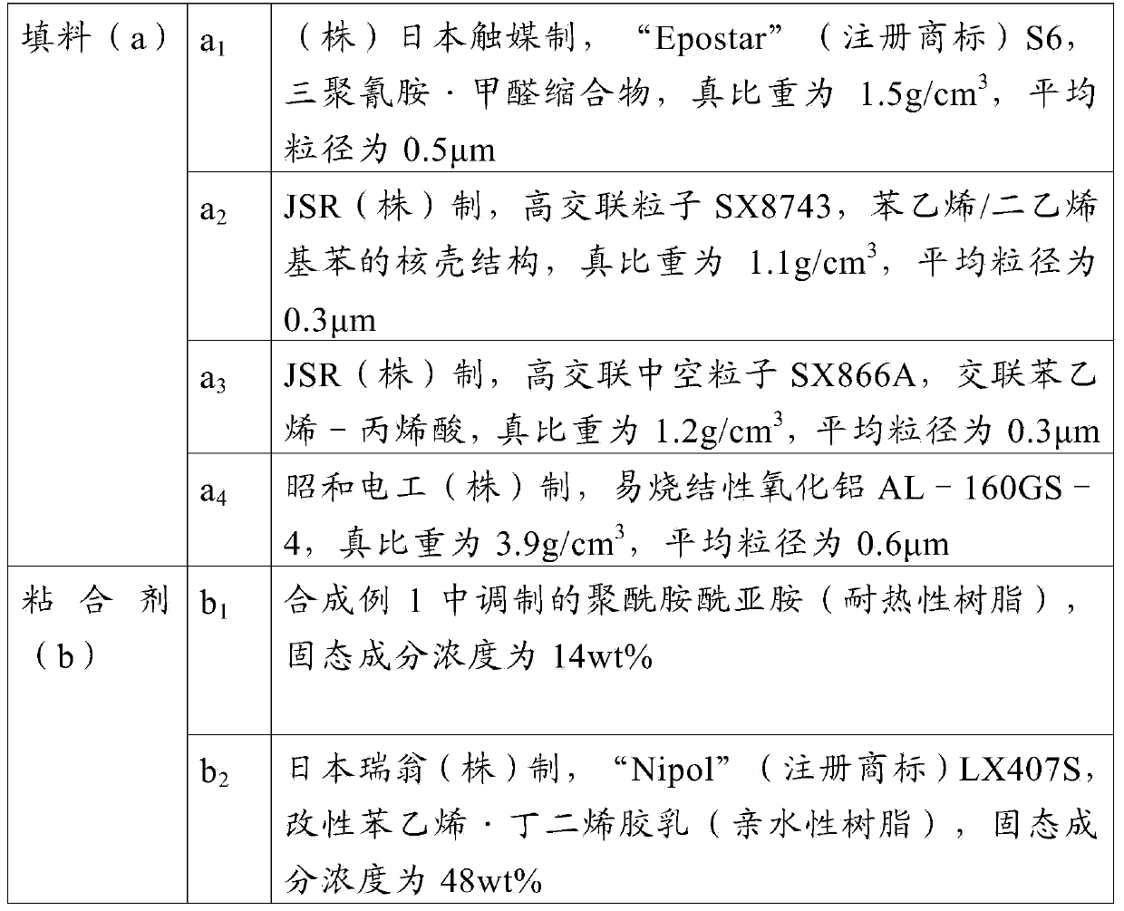
[0105] Here, a porous polyethylene film (thickness: 16 μm, air impermeability: 110 sec / 100ccAir, porosity: 48%) was used as the polyolefin porous film A to produce a laminated porous film. The physical properties of the polyethylene porous membrane will be described later.
Synthetic example 1
[0107] Synthesis of heat-resistant resin (polyamideimide)
[0108] 1 mole of trimellitic anhydride (TMA), 0.8 mole of ortho-toluene diisocyanate (TODI), 0.2 mole of 2,4-toluene diisocyanate (TDI), 0.01 mole of potassium fluoride and N-methyl-2-pyrrolidone Put them together into a four-necked flask with a thermometer, a cooling tube, and a nitrogen gas introduction tube, wherein the solid content concentration was 20%, stirred at 100°C for 5 hours, and then diluted with N-methyl-2-pyrrolidone to make the solid content The concentration was changed to 14%, and a polyamideimide resin solution (a) was synthesized. The inherent viscosity of the obtained polyamide-imide resin was 1.35 dL / g, and the glass transition temperature was 320°C.
[0109] Preparation of varnish for forming porous layer B
[0110] According to the compounding ratio shown in Table 2, the binder resin (b), filler (a), solvent, and zirconia beads (Toray Co., Ltd. "Torayceram" (registered trademark) beads, diam...
Embodiment 1~3 and comparative example 2
[0112] Lamination of porous layer B containing heat-resistant resin as binder (b)
[0113] Using the above-obtained varnish, apply it on the polyolefin porous membrane A by the knife coating method, and pass through it in 8 seconds at a temperature of 25°C and an absolute humidity of 1.8g / m 3 The low humidity area, followed by 5 seconds through the temperature of 25 ℃, absolute humidity of 12g / m 3 The high-humidity zone, and then immersed in an aqueous solution containing 5% by weight of N-methyl-2-pyrrolidone for 10 seconds, washed with pure water, and then dried by a hot air drying oven at 70°C to obtain a laminated porous membrane. At this time, the gap of the doctor blade is adjusted so that the dry film thickness of the porous layer B becomes a predetermined thickness.
PUM
| Property | Measurement | Unit |
|---|---|---|
| particle size | aaaaa | aaaaa |
| thickness | aaaaa | aaaaa |
| glass transition temperature | aaaaa | aaaaa |
Abstract
Description
Claims
Application Information
 - R&D
- Intellectual Property
- Life Sciences
- Materials
- Tech Scout
- Unparalleled Data Quality
- Higher Quality Content
- 60% Fewer Hallucinations
Browse by: Latest US Patents, China's latest patents, Technical Efficacy Thesaurus, Application Domain, Technology Topic, Popular Technical Reports.
© 2025 PatSnap. All rights reserved.Legal|Privacy policy|Modern Slavery Act Transparency Statement|Sitemap|About US| Contact US: help@patsnap.com


