
Welding Process and Welding Mechanism of Microwave Substrate and Housing

A microwave substrate and welding process technology, applied in welding equipment, manufacturing tools, metal processing equipment, etc., can solve problems such as cracks at the joints of microwave substrates, affecting component reliability, differences in thermal expansion coefficients between microwave substrates and solder, etc., to achieve The process flow is convenient and feasible, the effect of improving grounding and heat dissipation performance, improving electrical performance and reliability

Active Publication Date: 2017-08-29
SHANGHAI SPACEFLIGHT ELECTRONICS & COMM EQUIP RES INST
View PDF3 Cites 0 Cited by
  • Summary
  • Abstract
  • Description
  • Claims
  • Application Information

AI Technical Summary

Problems solved by technology

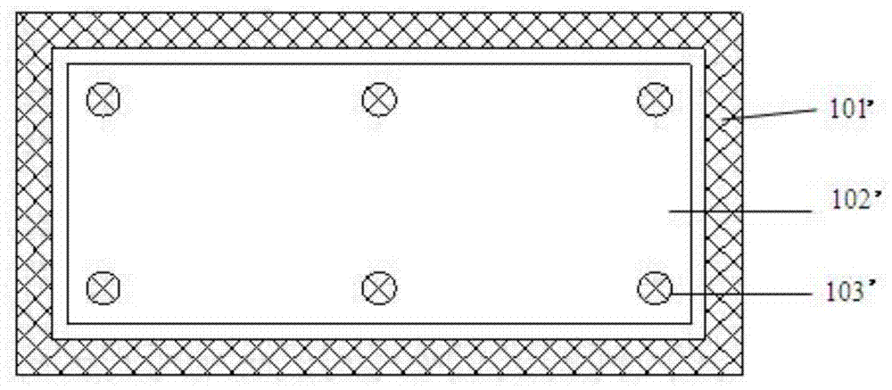
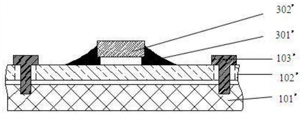
For general microwave components, this welding method can already meet the requirements, but the commonly used housing materials are generally aluminum and copper, and their thermal expansion coefficients are 23ppm (one millionth) and 15ppm, and the thermal expansion coefficient of tin-based solder is 25ppm Or so, the thermal expansion coefficient of the general microwave substrate material is 4-8ppm, there is a large difference in the thermal expansion coefficient of the microwave substrate and the solder, and cracks are prone to appear at the connection between the microwave substrate and the solder during the hot and cold cycle, and the appearance of such cracks will definitely cause affect the reliability of components

Method used


Image

  • Welding Process and Welding Mechanism of Microwave Substrate and Housing
  • Welding Process and Welding Mechanism of Microwave Substrate and Housing
  • Welding Process and Welding Mechanism of Microwave Substrate and Housing

Examples


Embodiment 1

[0046] as attached Figure 5-13 As shown, the present invention relates to a welding process of a microwave substrate and a housing, comprising the following steps:

[0047]Some through holes 801 are processed on the microwave substrate 102. These through holes can be circular through holes, polygonal through holes, irregular through holes, etc., and are not limited, but for the convenience of processing and cost saving, in this embodiment Circular through holes are adopted, and of course the positions of these through holes do not affect the wiring of the microwave substrate.

[0048] A cylinder 601 corresponding to a through hole is processed on the inner bottom surface of the housing 101, the through hole can be used for the cylinder to penetrate, and the aperture of the through hole is larger than the diameter of the cylinder, where the aperture refers to the diameter of the largest diameter cylinder that the through hole can pass through , in this embodiment, the cylinde...

Embodiment 2

[0058] On the basis of Embodiment 1, some pressure-bearing platforms 1101 with uniform height and larger diameter are evenly made on the upper surface of the microwave substrate. The table height is higher than the circuit traces and components on the microwave substrate, generally greater than 0.5mm. The pressure-bearing table can be a cylindrical surface, and the second pressure block 1201 applies pressure on the microwave substrate through these cylindrical surfaces, thereby ensuring the microwave substrate. Surface cleanliness.

[0059] Applying pressure 1102 can be to apply pressure to the second briquetting block by means of a cylinder, or use a frame beam on the top of the shell, apply pressure to put the shell into the bottom plate, fix the frame beam on the bottom plate, and do it on the beam. out of the screw hole, the screw goes through the screw hole on the beam and against the second pressure block, turn the screw joint to adjust the applied pressure, as shown in ...

Embodiment 3

[0061] like Figure 6-9 As shown, the welding mechanism obtained in the first or second embodiment above includes a microwave substrate 102, a housing 101 and a solder layer 501; a through hole 801 is provided on the microwave substrate, and these through holes 801 can be circular Through holes, polygonal through holes, irregular through holes, etc. are not limited, but in order to facilitate processing and save costs, circular through holes are used in this embodiment. Of course, the positions of these through holes do not affect the wiring of the microwave substrate. The inner bottom surface of the housing is provided with a cylinder corresponding to the through hole. The through hole penetrates into the cylinder. The diameter of the through hole is larger than the diameter of the cylinder, and the height of the cylinder is smaller than the thickness of the microwave substrate. In this embodiment, the cylinder It is a cylinder 601, its diameter is smaller than the diameter o...


PUM

PropertyMeasurementUnit
thicknessaaaaaaaaaa
diameteraaaaaaaaaa

Abstract

The invention relates to a welding process and a welding mechanism for a microwave substrate and a housing. The process comprises machining a through hole in the microwave substrate, and machining a column on the inner bottom surface of the housing, which corresponds to the through hole, wherein the through hole can be penetrated by the column, the diameter of the through hole is larger than that of the column, and the height of the column is smaller than the thickness of the microwave substrate; forming integrated metalized layers on the surfaces of both the microwave substrate and the housing; placing the microwave substrate, solder blocks and the housing correspondingly and sequentially from top to bottom, performing reflow soldering on the microwave substrate and the housing, and during the reflow soldering process, exerting pressure on the upper surface of the microwave substrate to guarantee fitting of the microwave substrate and the housing. The welding process of the microwave substrate and the housing can improve the welding firmness of the substrate and the housing, guarantee the cleanliness of the upper surface of the substrate, improve the grounding and radiating performance of the substrate and further improve the electrical performance and the reliability of components.

Description

technical field [0001] The invention relates to a welding process and a welding mechanism thereof, in particular to a welding process and a welding mechanism of a microwave substrate and a shell in a microwave component. Background technique [0002] A microwave component is a microwave integrated circuit functional module. Microelectronic packaging technology is usually used to connect the microwave substrate in the housing, and then integrate the components (resistors, capacitors, inductors, chips, etc.) that constitute the circuit on the microwave substrate to form A circuit with some microwave function. Microwave components are widely used in the fields of aviation communication, aerospace measurement and control, and radar reconnaissance. In microwave components, the upper surface of the microwave substrate is welded with components, and the wiring on the microwave substrate transmits electrical and microwave signals. Therefore, the reliability of the microwave substra...

Claims


Application Information

Patent Timeline
Patent Type & Authority Patents(China)
IPC IPC(8): H05K3/34B23K1/20B23K3/08
Inventor 曹向荣王立春周义符容
Owner SHANGHAI SPACEFLIGHT ELECTRONICS & COMM EQUIP RES INST
Learn More