
Synergistic removal system and method for realizing ultra-low emission of multiple pollutants of smoke of thermal power plant

A technology for pollutants and thermal power plants, applied in combustion methods, combustion using block fuels and gaseous fuels, combustion using liquid fuels and gaseous fuels, etc., can solve the problems of reduced boiler combustion efficiency, high ammonia escape, and urea consumption Large and other problems, to achieve the effect of improving dust removal efficiency, ultra-low emissions, and reducing specific resistance

Inactive Publication Date: 2014-10-15
XIAN TPRI BOILER ENVIRONMENTAL PROTECTION ENG CO LTD +1
View PDF4 Cites 32 Cited by
  • Summary
  • Abstract
  • Description
  • Claims
  • Application Information

AI Technical Summary

Problems solved by technology

However, the adoption of low-nitrogen combustion technology may have some impact on boiler performance: boiler combustion efficiency may be reduced, causing problems such as slagging and corrosion on the heating surface of the water wall in the burner area
The main problem of SNCR denitration system in practical application is that the denitration efficiency is not high (about 15% to 50%), and the larger the boiler capacity, the lower the SNCR denitration efficiency
In addition, the utilization rate of urea is low (about 15%-30%), and the large consumption of urea leads to high ammonia slip (about 5-10ppm)
When SNCR denitrification is used alone, ammonia slip and SO in flue gas 3 The ammonium bisulfate produced by the reaction will cause fouling, dust accumulation and blockage on the heating surface of the air preheater

Method used


Image

  • Synergistic removal system and method for realizing ultra-low emission of multiple pollutants of smoke of thermal power plant

Examples


Embodiment Construction

[0026] The present invention will be described in further detail below in conjunction with the accompanying drawings.

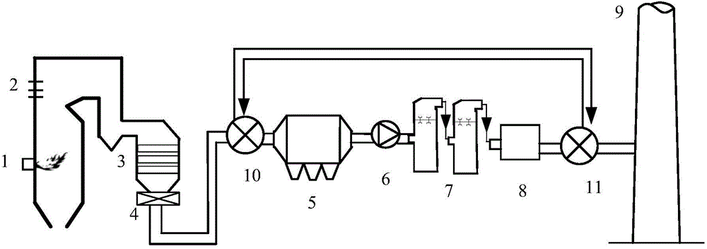
[0027] On the premise of meeting the ultra-low emission requirements, the present invention needs to optimize the overall environment protection facilities in order to minimize the impact of the operation of the environment protection facilities on the thermal efficiency of the boiler, the plant power consumption rate and the unit efficiency. At the same time, the invention is applicable to new coal-fired units and old coal-fired units, and can regard the environmental protection facilities of the power plant as an organic whole, and has the advantages of reliable technical route, advanced environmental protection indicators, low overall investment level, and significant energy saving and consumption reduction. For old coal-fired units, it is necessary to transform them based on existing environmental protection facilities to save costs. For new coal-fired un...


PUM


Abstract

The invention discloses a synergistic removal system and method for realizing ultra-low emission of multiple pollutants of smoke of a thermal power plant. By the aid of a synergistic dust-removal system consisting of a smoke cooler, an efficient dust remover, an efficient wet desulphurization system and a wet type electric dust remover, the total particulate matter emission in a chimney can be controlled within 5 mg / m<3>. By the aid of a synergistic mercury-removal system consisting of a selective catalytic reduction denitration system, the efficient dust remover, the efficient wet desulphurization system and the wet type electric dust remover, the emission concentration of mercury in the smoke at the chimney can be lower than 6 mu g / m<3>. By the aid of an efficient denitration system consisting of a low-nitrogen burner, a selective non-catalytic reduction denitration system and the selective catalytic reduction denitration system, the NOx concentration can be controlled within 50 mg / m<3>. A two-stage circulation two-tower limestone-gypsum wet desulphurization system is used, a rotary gas-to-gas heat exchanger is cancelled, the leakage of the original smoke to clean smoke is avoided, and the concentration of SO2 in the smoke can be controlled within 35 mg / m<3>. Besides, the synergistic removal system and method are low in overall investment level, and waste heat in the smoke can be recycled to reduce the energy consumption.

Description

technical field [0001] The invention belongs to the field of removal of atmospheric pollutants, and in particular relates to a coordinated removal system and method for realizing ultra-low emission of multi-pollutants in flue gas of a thermal power plant. Background technique [0002] Following the announcement of the State Council on Air Pollution Prevention and Control Action Plan Guofa [2013] No. 37 "Air Pollution Prevention and Control Action Plan", the state has recently introduced a series of environmental protection policies: the National Energy Administration issued "Strengthening the Energy Industry" on January 23. The Air Pollution Prevention and Control Work Plan, the Measures for the Supervision of Environmental Protection Electricity Prices for Coal-fired Generating Sets and the Operation of Environmental Protection Facilities have been implemented since May 1, 2014, and the new version of the "Emission Standards of Air Pollutants for Thermal Power Plants" will b...

Claims


Application Information

Patent Timeline
IPC IPC(8): F23C5/08F23J15/00
Inventor 王月明牛国平何育东聂孝峰张广才董康田
Owner XIAN TPRI BOILER ENVIRONMENTAL PROTECTION ENG CO LTD
Learn More