Fuel manifold joint for gas turbine and gas turbine

A gas turbine and fuel manifold technology, which is applied to gas turbine installations, machines/engines, mechanical equipment, etc., can solve the problems of complex fuel manifold joint structure, poor thread structure maintenance, etc., so as to improve fuel supply efficiency, reduce processing costs, and reduce fuel oil. The effect of the chance of leakage

Active Publication Date: 2014-09-03
CHINA AVIATION POWER MACHINE INST
View PDF4 Cites 1 Cited by
  • Summary
  • Abstract
  • Description
  • Claims
  • Application Information

AI Technical Summary

Problems solved by technology

[0003] The purpose of the present invention is to provide a fuel oil main pipe joint for a gas turbine and a gas turbine to solve the technical problems that the existing fuel main pipe joint has a complicated structure and poor maintainability by using a threaded structure for connection

Method used


Image

  • Fuel manifold joint for gas turbine and gas turbine
  • Fuel manifold joint for gas turbine and gas turbine
  • Fuel manifold joint for gas turbine and gas turbine

Examples


Embodiment Construction

[0025] The embodiments of the present invention will be described in detail below with reference to the accompanying drawings, but the present invention can be implemented in various ways defined and covered.

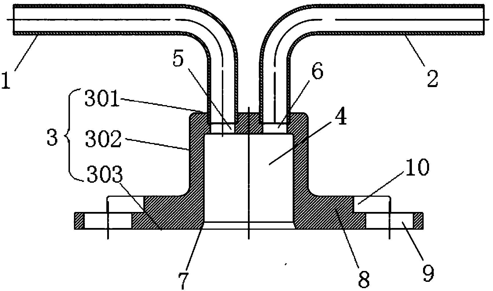
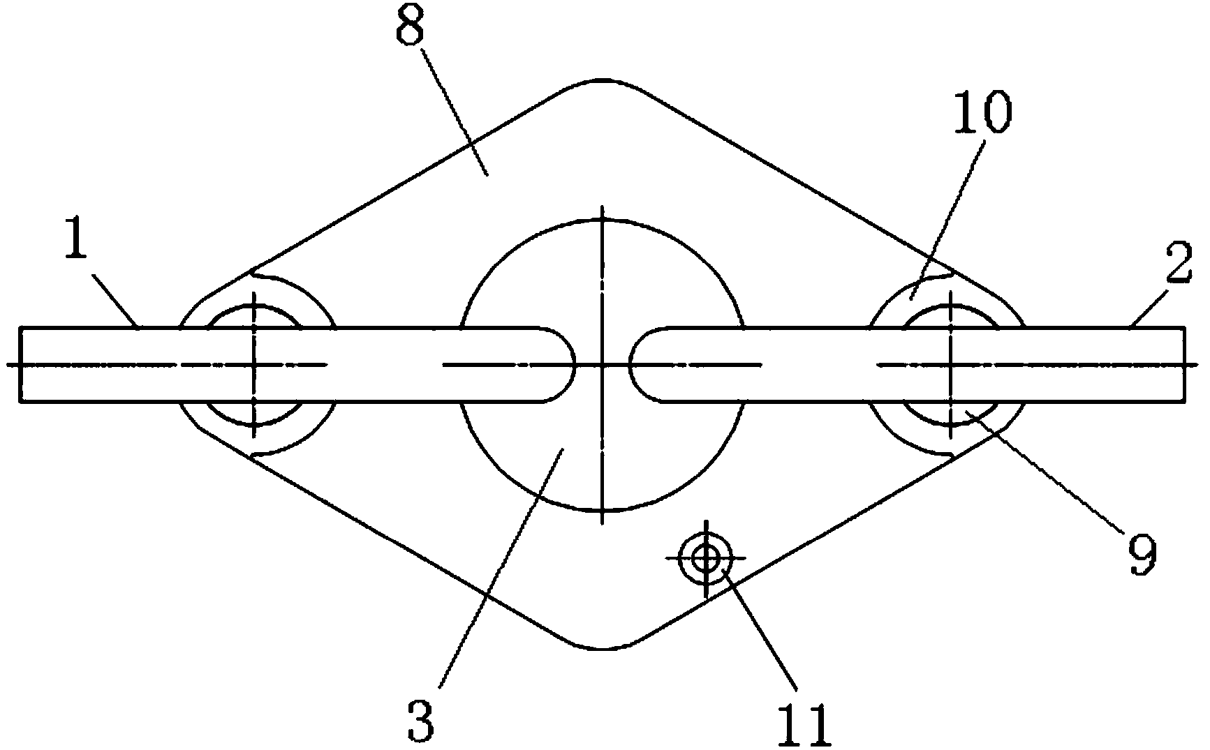
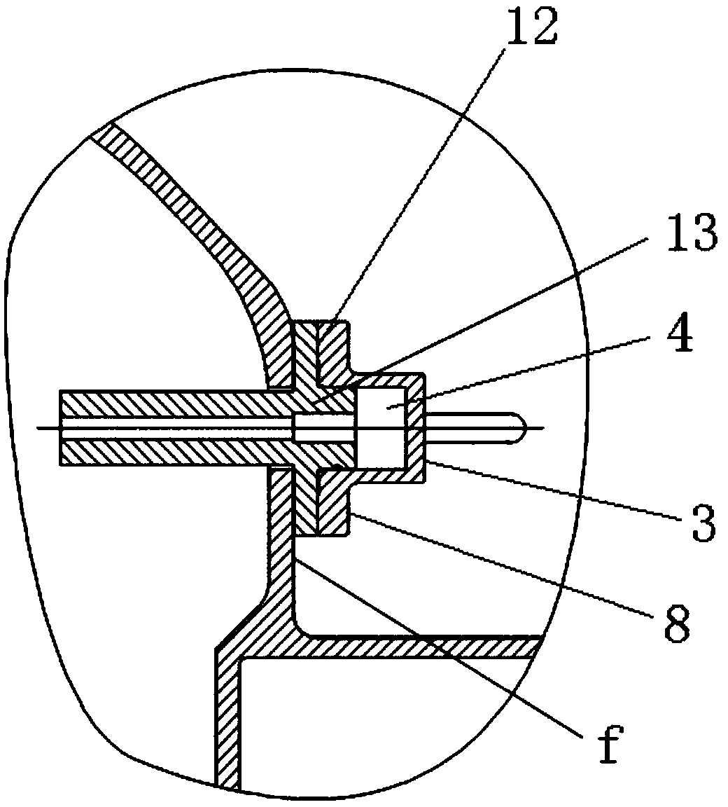
[0026] figure 1 It is one of the structural schematic diagrams of the fuel oil main pipe joint used in the gas turbine according to the preferred embodiment of the present invention; figure 2 It is the second structural schematic diagram of the fuel oil main pipe joint used in the gas turbine according to the preferred embodiment of the present invention; image 3 It is one of the schematic diagrams of the installation structure of the fuel oil main pipe joint used in the preferred embodiment of the present invention; Figure 4 It is the second schematic diagram of the installation structure of the fuel main pipe joint used in the gas turbine according to the preferred embodiment of the present invention.

[0027] Such as figure 1 and figure 2 As shown, the fuel...


PUM


Abstract

The invention discloses a fuel manifold joint for a gas turbine and the gas turbine. The fuel manifold joint comprises an oil inlet pipe, an oil outlet pipe and a nozzle joint, wherein the oil inlet pipe is connected with an external oil way, and the oil outlet pipe is used for supplying oil for a fuel nozzle at the downstream of the oil way; the nozzle joint is used for mounting the fuel nozzle and comprises an upper wall face, a side wall face and a mounting end face used for mounting in a fitting manner; one or more blind holes connected wit the input end of the fuel nozzle in a sealing manner are formed in the mounting end face of the nozzle joint; the input end of the fuel nozzle closes an opening of the blinding hole, and a fuel buffer cavity is formed in the blind hole; an oil inlet pipe access opening leading to the fuel buffer cavity is formed in the upper wall face or the side wall face of the nozzle joint, and the oil inlet pipe is connected into the oil inlet pipe access opening in the sealing manner; an oil outlet pipe access opening leading to the fuel buffer cavity is formed in the upper wall face or the side wall face of the nozzle joint, and the oil outlet pipe is connected into the oil outlet pipe access opening in the sealing manner. The fuel manifold joint has the advantages of simple structure, convenience in dismounting and mounting and reliability in use, and the machining cost and the maintenance cost are reduced.

Description

technical field [0001] The invention relates to the field of gas turbines, in particular to a fuel oil main pipe joint for gas turbines. Furthermore, the present invention also relates to a gas turbine comprising the above fuel manifold joint for a gas turbine. Background technique [0002] Fuel nozzles and fuel manifolds are important components in the combustion chamber of gas turbines. After passing through the fuel manifolds and fuel nozzles, the fuel enters the combustion chamber for combustion to provide the energy required for the turbine to do work. The current connection between the fuel nozzle and the fuel main pipe is threaded with the fuel nozzle by a threaded joint. Figure 5 It is the fuel main pipe joint of a certain type of gas turbine combustor, which is composed of oil supply pipe a, connecting elbow b, oil line joint c, steel wire retaining ring d, outer casing nut e, oil supply pipe a, connecting elbow b and oil line joint c is connected together by weld...

Claims


Application Information

Patent Timeline
Patent Type & Authority Applications(China)
IPC IPC(8): F02C7/22F02C7/20
Inventor 吴施志王朝晖张帆陈盛张德宝彭中九鲁婷婷
Owner CHINA AVIATION POWER MACHINE INST
Why Eureka
Try Eureka