Al technical title is built by PatSnap Al team. It summarizes the technical point description of the patent document.
A thin-layer and equipment technology, applied in the field of vertical sludge thin-layer drying equipment, can solve the problems of large heat loss, low heat transfer efficiency, and high dust volume, and achieve the effect of low heat loss and high heat transfer efficiency
Active Publication Date: 2015-05-27
CHONGQING UNIV
View PDF7 Cites 0 Cited by
Summary
Abstract
Description
Claims
Application Information
AI Technical Summary
This helps you quickly interpret patents by identifying the three key elements:
Problems solved by technology
Method used
Benefits of technology
Problems solved by technology
Existing drying technologies and equipment such as drum sludge drying equipment and multi-stage disc sludge drying equipment mainly rely on sludge back-mixing, and fluidized bed sludge drying equipment relies on convective heat transfer. They all have the disadvantages of low heat transfer efficiency, large heat loss, and high dust content. At present, the sludge thin-layer drying technology is an efficient, energy-saving, safe and environmentally friendly technology to solve the above problems.
Method used
Image
Click on the blue label to locate the original text in one second.
Reading with bidirectional positioning of images and text.
Examples
Embodiment
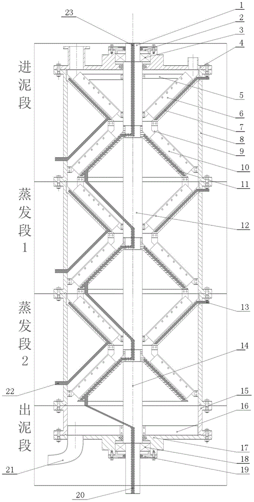
[0019] The sludge thin-layer drying equipment involved in this embodiment is an example of a sewage treatment plant treating sludge with a water content of 85% to 70%. The overall structure of the equipment is as follows figure 1 As shown, the equipment consists of mud inlet section, evaporation section and mud outlet section:
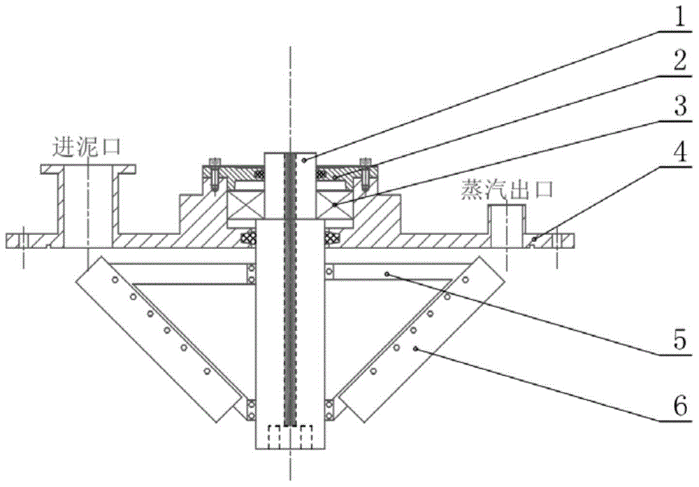
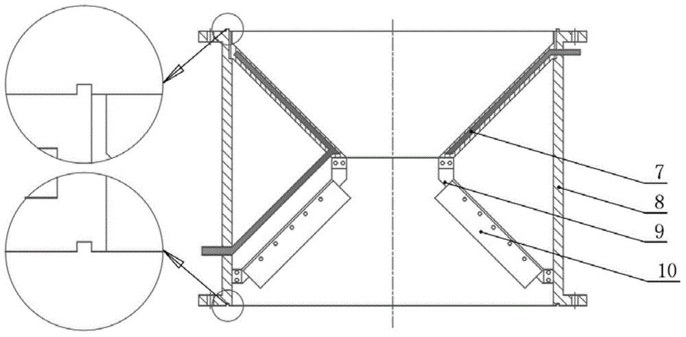
[0020] The mud inlet section is composed of a mud inlet flange 4, an evaporation cylinder 8, an oil chamber outer tank 7, an oil chamber inner tank 11, a fixed scraper 10, a rotating scraper 6, a mud inlet shaft 1, and an evaporation shaft 12. The mud inlet flange 4 is connected to the mud inlet section shaft 1 through the mud inlet section bearing 3, the mud inlet flange 4 is provided with a mud inlet and a steam outlet, and an oil passage is arranged in the mud inlet section shaft 1. The head part is provided with a rotating heat transfer oil outlet 23, the mud inlet flange 4 is connected with the evaporation cylinder 8 by screws, the upper part of t...
PUM
Abstract
The invention discloses a vertical type sludge thin layer drying device, which comprises a sludge inlet section, an evaporation section, a sludge outlet section and a heat conduction oil pipe, wherein the sludge inlet section and the evaporation section form a heating cabin, a rotary main shaft with a rotary scraper and an oil cavity liner is arranged in the heating cabin, the rotary main shaft is composed of a sludge inlet section shaft, an evaporation section shaft and a sludge outlet section shaft, an evaporation cylinder of the heating cabin is provided with a fixed scraper, the evaporation cylinder is provided with an oil cavity outer container, and a fixed heat conduction oil inlet in the evaporation cylinder, a fixed heat conduction oil outlet in the evaporation cylinder, the oil cavity outer container and an oil pipe form a fixed oil line system; an oil line is arranged in the evaporation section shaft, the sludge inlet section shaft is provided with a rotary heat conduction oil outlet, the sludge outlet section shaft is provided with a rotary heat conduction oil inlet, and the rotary heat conduction oil inlet, the rotary heat conduction oil outlet, the oil line in the shaft, an oil cavity container and an oil pipe form a rotary oil path system; a flange of the sludge inlet section is provided with a sludge inlet and a steam outlet, and a flange on the sludge outlet section is provided with a sludge outlet. The heat transfer efficiency in the drying process is high, the heat loss is relatively low, the dust is basically avoided, the drying process is independent of dry sludge backmixing, and the sludge with water content of 85-70% can be dried to water content of 50-35%.
Description
technical field [0001] The invention belongs to the technical field of urban sewage sludge drying, and in particular relates to a vertical sludge thin-layer drying equipment. Background technique [0002] With the development of my country's economy, the discharge of urban wastewater is increasing day by day, and the production capacity of sludge plants has also been greatly increased. Sludge treatment and disposal have gradually become the focus of attention at home and abroad. At present, the sludge disposal methods in my country mainly include sanitary landfill, composting, direct land use and incineration. The water content of sludge is the key to restricting sludge disposal. The water content of sludge from 95% to 60% is the starting point of landfill and composting, and from 95% to 50% is the starting point of incineration. The traditional mechanical dehydration method can reduce the moisture content of the sludge to about 75%. To further reduce the moisture content, ...
Claims
Application Information
Patent Timeline
Application Date:The date an application was filed.
Publication Date:The date a patent or application was officially published.
First Publication Date:The earliest publication date of a patent with the same application number.
Issue Date:Publication date of the patent grant document.
PCT Entry Date:The Entry date of PCT National Phase.
Estimated Expiry Date:The statutory expiry date of a patent right according to the Patent Law, and it is the longest term of protection that the patent right can achieve without the termination of the patent right due to other reasons(Term extension factor has been taken into account ).
Invalid Date:Actual expiry date is based on effective date or publication date of legal transaction data of invalid patent.