A vertical vacuum sputtering coating production line

A coating production line and vacuum sputtering technology, which is applied in sputtering coating, vacuum evaporation coating, ion implantation coating, etc., can solve the problems of failure to improve target utilization, increased difficulty, and high equipment cost

Active Publication Date: 2016-03-09
XIANGTAN HONGDA VACUUM TECH CO LTD
View PDF8 Cites 1 Cited by
  • Summary
  • Abstract
  • Description
  • Claims
  • Application Information

AI Technical Summary

Problems solved by technology

However, the cathode device is affected by its own dimensional accuracy and strong magnetic attraction, especially during installation, the assembly accuracy is difficult to meet the design accuracy requirements
Chinese patent CN201778106U discloses a rectangular planar magnetron cathode structure in vacuum coating equipment. This cathode structure solves the above problems to a certain extent, but its target utilization rate still cannot achieve a qualitative leap
Chinese patent CN201770767U discloses a vacuum coating cathode device. The main technical problem solved by this patent is to simplify the process of replacing the target, save the time required for replacing the target, and does not solve the technical problem of low target utilization.
Chinese patent CN201981253U discloses a rectangular planar magnetron sputtering cathode. For the shortcomings of the sputtering cathode with an anode frame, the anode frame is canceled and the structure is simplified; in addition, the structure of the shield is improved to avoid the problem of grounding of the shield ; The improvement of the planar cathode still fails to increase the utilization rate of the target
However, because the signals of the substrate entering and exiting cannot be accurately received, and the human-controlled action has a certain delay, it is usually impossible to open the inlet and outlet gate valves in a timely manner, which reduces production efficiency.
In addition, the vacuum coating production line has very high requirements on the vacuum environment, so the thickness of the door body of the vacuum chamber will increase. Correspondingly, the thickness of the gate valves at the entrance and exit of the production line will increase, and the difficulty of manual operation will increase.
[0004] With the rapid development of coating technology in the field of vacuum coating, the requirements for coating products are getting higher and higher. Therefore, more and more improvements have occurred in the coating production line, and the requirements of the production line have increased accordingly. The overall stability of the coating production line in the prior art stability and coating uniformity, low production efficiency and high equipment cost; and most of the existing coating production lines can only meet the coating of one target material, or the entire production line is only suitable for one type of target material, which cannot meet the current requirements. Therefore, there is an urgent need for a coating production line that can adapt to a variety of targets and the entire coating process is easy to operate

Method used


Image

  • A vertical vacuum sputtering coating production line
  • A vertical vacuum sputtering coating production line
  • A vertical vacuum sputtering coating production line

Examples


Embodiment Construction

[0208] Hereinafter, the present invention will be further described in detail and completely in combination with the embodiments and the drawings.

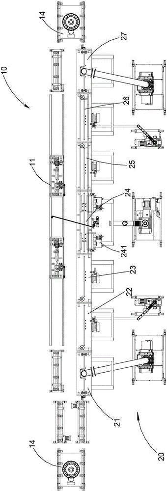
[0209] Figure 1 to Figure 29 , Is a schematic diagram of a preferred embodiment of the vertical vacuum sputtering coating production line provided by the present invention. Such as figure 1 As shown, the coating production line includes a transmission line 10 and a coating line 20. The transmission line 10 and the coating line 20 are connected. In order to save floor space and improve work efficiency, the transmission line 10 and the coating line 20 are arranged in parallel.

[0210] The coating line 20 includes an inlet chamber 21, an inlet transition chamber 22, an inlet buffer chamber 23, a coating chamber 24, an outlet buffer chamber 25, an outlet transition chamber 26 and an outlet chamber 27, an inlet chamber 21, an inlet transition The chamber 22, the inlet buffer chamber 23, the coating chamber 24, the outlet buffer chamber 25...


PUM


Abstract

The invention discloses a vertical vacuum sputtering coating production line, which includes a transfer line and a coating line, the coating line is connected to the transfer line; the transfer line includes a track, at least one transfer car and at least one film loading device, the transfer car Running on the above track, the film loading device is transferred by the transfer car; the coating line includes an inlet chamber, an inlet transition chamber, an inlet buffer chamber, a coating chamber, an outlet buffer chamber, an outlet transition chamber and One exit chamber. Compared with the existing technology, the transmission line and the coating line are connected end to end to form a circular line, which saves floor space. The substrate transmission in the entire coating production line adopts intelligent control, which saves manpower and material resources and improves production efficiency. Each chamber in the coating line is based on Product demand is replaced or increased, and the entire coating production line can adapt to various coating process requirements, prolong the service life, and save resources, so its application prospect is very broad.

Description

Technical field [0001] The invention relates to the technical field of vacuum coating, in particular to a vertical vacuum sputtering coating production line. Background technique [0002] Vacuum coating technology first appeared in the 1930s, industrial applications began to appear in the 1940s and 1950s, and large-scale industrial production began in the 1980s. It has been widely used in industries such as electronics, aerospace, packaging, decoration, and hot stamping. Vacuum coating technology is a novel material synthesis and processing technology, and it is an important part of the field of surface engineering technology. Vacuum coating technology is the use of physical and chemical means to coat a solid surface with a special performance coating, so that the solid surface has wear resistance, high temperature resistance, corrosion resistance, oxidation resistance, radiation protection, conductivity, magnetic conductivity, insulation and decoration Many lights are superior ...

Claims


Application Information

Patent Timeline
Patent Type & Authority Patents(China)
IPC IPC(8): C23C14/34C23C14/35C23C14/56
CPCC23C14/35C23C14/56
Inventor 黄国兴孙桂红祝海生黄乐梁红吴永光
Owner XIANGTAN HONGDA VACUUM TECH CO LTD
Why Eureka
Try Eureka