
CNC gear hobbing machine hob spindle mechanism

A gear hobbing machine and hob technology, applied in the field of gear hobbing machines, can solve the problems of low structural strength, relatively high requirements on spindle rigidity and rotational speed, and high manufacturing cost, achieve stability and anti-deformation ability, realize automatic production requirements, and reduce production costs. Effect

Inactive Publication Date: 2016-09-14
浙江嘉力宝精机股份有限公司
View PDF5 Cites 0 Cited by
  • Summary
  • Abstract
  • Description
  • Claims
  • Application Information

AI Technical Summary

Problems solved by technology

Existing gear hobbing machines have been widely used in various machinery manufacturing industries such as automobiles, tractors, machine tools, construction machinery, mining machinery, metallurgical machinery, petroleum, instrumentation, aircraft and spacecraft. Processing of gears, while the gears processed by the hob are generally interrupted cutting, the impact force on the hob spindle changes greatly and rapidly, and the requirements for the rigidity and speed of the spindle are relatively high. At the same time, the existing CNC gear hobbing machines also have significant shortcomings: for example, the overall The structure of the hob is complex and difficult to manufacture. In addition, the hob spindle mechanism has high manufacturing cost, poor rigidity, and low speed, which cannot meet the needs of automation well, and virtually reduces work efficiency and part accuracy; in order to solve the problems existing in the prior art problem, people have explored it for a long time, and proposed various solutions
[0004] The above-mentioned scheme has improved some problems of the prior art to a certain extent, but there are at least the following defects in this scheme: 1. The design is unreasonable, and its structural strength is low and the rigidity is poor during interrupted cutting, which virtually reduces the The speed of the main shaft is poor in practicability; 2. The structure is complex and the volume is large; 3. The installation is inconvenient

Method used


Image

  • CNC gear hobbing machine hob spindle mechanism

Examples


Embodiment Construction

[0020] The present invention will be described in further detail below in conjunction with the accompanying drawings and specific embodiments.

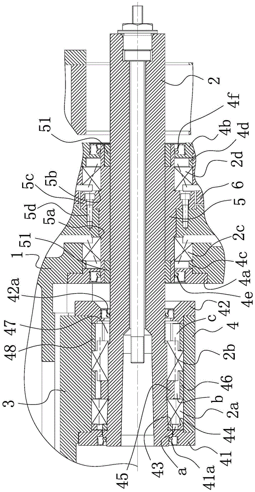
[0021] Such as figure 1 As shown, the hob spindle mechanism of the CNC gear hobbing machine includes a tool holder housing 1 and a hob cutter spindle 2 which is penetrated in the tool holder housing 1 and can rotate relative to the tool holder housing 1. The front end of the hob spindle 2 is inserted into the The tool holder housing 1 is suspended and set, the tail end passes through the tool holder housing 1 and the end extends to the outside of the tool holder housing 1, and a first rolling structure is provided between the tool holder housing 1 and the hob spindle 2 , a supporting plate 3 fixedly connected with the tool rest housing 1 is provided in the tool post housing 1, and a cylindrical tube that is fixedly connected with the supporting plate 3 and sleeved on the periphery of the free end of the hob spindle 2 is provided on th...


PUM


Abstract

The invention belongs to the technical field of gear hobbing machines, and particularly relates to a hobbing cutter main shaft mechanism of a CNC gear hobbing machine. The hobbing cutter main shaft mechanism of the CNC gear hobbing machine solves the technical problems that practicability is poor in the prior art and the like. The hobbing cutter main shaft mechanism of the CNC gear hobbing machine comprises a cutter rest shell and hobbing cutter main shaft which is arranged in the cutter rest shell in a penetrating mode and can rotate relative to the cutter rest shell, the front end of the hobbing cutter main shaft is inserted into the cutter rest shell and is arranged in a suspending mode, the tail end of the hobbing cutter main shaft penetrates through the cutter rest shell and extends out of the cutter rest shell, a first rolling structure is arranged between the cutter rest shell and the hobbing cutter main shaft, a supporting plate fixedly connected with the cutter rest shell is arranged in the cutter rest shell and is provided with a barrel-shaped locating body which is fixedly connected with the supporting plate and arranged on the periphery of the suspended end of the hobbing cutter main shaft in a sleeved mode, a second rolling structure is arranged between the hobbing cutter main shaft and the barrel-shaped locating body, and an axial locating mechanism used for preventing axial float of the hobbing cuter is further arranged between the hobbing cutter main shaft and the barrel-shaped locating body. The hobbing cutter main shaft mechanism of the CNC gear hobbing machine has the advantages of being high in structural intensity, rigidity and practicability during interrupted cutting.

Description

technical field [0001] The invention belongs to the technical field of gear hobbing machines, in particular to a hob spindle mechanism of a numerically controlled gear hobbing machine. Background technique [0002] Gear hobbing machine is the most widely used machine tool in gear processing machine tools. It can cut straight teeth and helical cylindrical gears, and can also process worm gears and sprockets. It uses hobs to process straight teeth and helical gears according to the generation method. And herringbone cylindrical gear and worm gear processing machine tool, this machine tool can also process various special tooth-shaped workpieces such as splines and sprockets when using a special hob. Existing hobbing machines have been widely used in various machinery manufacturing industries such as automobiles, tractors, machine tools, engineering machinery, mining machinery, metallurgical machinery, petroleum, instrumentation, aircraft and spacecraft. Processing of gears, w...

Claims


Application Information

Patent Timeline
Patent Type & Authority Patents(China)
IPC IPC(8): B23B19/02
CPCB23Q1/70
Inventor 陈立新吴文杰
Owner 浙江嘉力宝精机股份有限公司
Learn More