
LTPS technology

A process and evaporation technology, applied in the field of LTPS process, can solve problems such as complex process, affecting product production yield, long production time, etc., and achieve the effect of reducing cost, shortening time and improving productivity

Inactive Publication Date: 2014-08-06
SICHUAN CCO DISPLAY TECH
View PDF4 Cites 4 Cited by
  • Summary
  • Abstract
  • Description
  • Claims
  • Application Information

AI Technical Summary

Problems solved by technology

[0005] The purpose of the present invention is to solve the shortcomings of the existing LTPS process, such as complicated procedures, long production time, and the process will affect the yield of the product, and simplify the manufacturing method of the repeated TFT process through the mask plate, and propose an LTPS process

Method used


Image

  • LTPS technology
  • LTPS technology
  • LTPS technology

Examples


Embodiment Construction

[0029] The following embodiments of the present invention are designed according to the principles of the present invention, and the present invention will be further described below in conjunction with the accompanying drawings and specific embodiments.

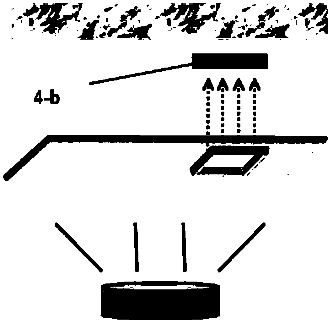
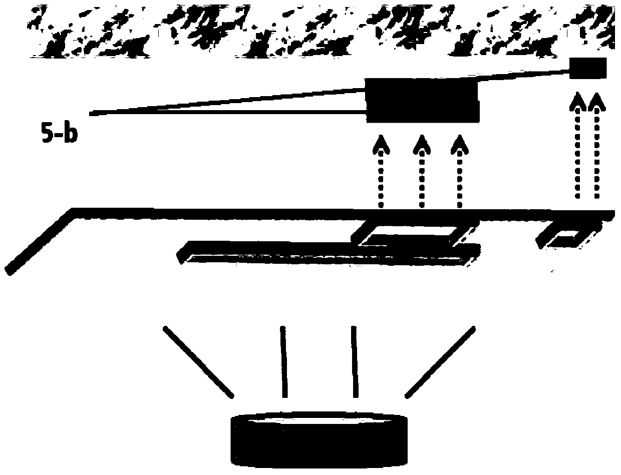
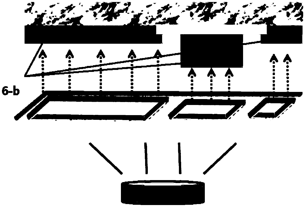
[0030] Such as Figures 1 to 5 As shown, the LTPS process of the present embodiment comprises steps as follows:

[0031] S1. On the glass substrate (heat treated at 600°C), the thickness of PECVD evaporation to prevent impurity penetration is buffer oxide layer;

[0032] S2. Using PECVD or LPCVD, the evaporation thickness is Single crystal silicon (a-Si) is used as the source and drain of the transistor (Transistor);

[0033] S3. In order to complete the LTPS non-laser (Non laser) method of silicon crystallization, ALD equipment is used to vapor-deposit Ni or sputter tens of atoms in atomic units. the Ni;

[0034] S4. Using a furnace (Furnace) to crystallize silicon under the condition of about 600° C. for one hour t...


PUM


Abstract

The invention relates to an LTPS technology. Compared with a traditional technology, the LTPS technology comprises the following steps that according to the type of a transistor, P- or B+ is doped to a source electrode or a drain electrode of the transistor; thermal treatment is conducted through a furnace to activate doped impurities; an oxide pattern with the thickness shown in the specification is formed through an electron beam evaporator and a mask plate in a vapor deposition mode, so that a gate electrode metal layer and the like are formed. The LTPS technology has the advantages that compared with an LTPS technology in the background art, cost is reduced and productivity is improved. The steps that a passivation insulation film with the thickness shown in the specification is formed through PECVD in a vapor deposition mode and a contact hole pattern for anode contact is formed through photoetching and etching are omitted, wherein the passivation insulation film can prevent an anode and a metal wire from generating a short circuit. The processes of vapor deposition, photoetching, etching and PR are simplified into a mask plate manufacturing process so that the time for manufacturing a TFT array set can be shortened and production cost can be reduced. The LTPS technology is not only suitable for the MIC but also suitable for the conditions of different crystallization methods such as MILC or MICC.

Description

technical field [0001] The invention belongs to the technical field of OLED flat display panel technology, and in particular relates to an LTPS technology. Background technique [0002] In flat panel display technology, Organic Light-Emitting Diode (OLED) displays are famous for their thinness, active light emission, fast response speed, wide viewing angle, rich colors and high brightness, low power consumption and high and low temperature resistance. It is recognized by the industry as the third generation of display technology after liquid crystal display (LCD). Active OLED (ActiveMatrix OLED, AMOLED) is also called active matrix OLED. AMOLED can realize large size and high The resolution panel is the focus of current research and the development direction of future display technology. [0003] In the existing low-temperature polysilicon (LTPS, Low Temperature Poly-silicon) manufacturing process, the main steps of thin film field effect transistor (TFT, Thin Film Transis...

Claims


Application Information

Patent Timeline
Patent Type & Authority Applications(China)
IPC IPC(8): H01L21/77
CPCH10K71/00H10K77/10Y02E10/549
Inventor 郎丰伟文东星
Owner SICHUAN CCO DISPLAY TECH
Learn More