Head replacement-type cutting tool

A cutting tool, exchange technology, applied in the direction of manufacturing tools, tool workpiece connection, metal processing equipment, etc., can solve problems such as breakage, cutting head breakout, cutting head idling, etc., to improve fracture toughness, reliable contact pressure, and improve thermal conductivity. rate effect

Active Publication Date: 2014-06-11
MITSUBISHI MATERIALS CORP
View PDF6 Cites 8 Cited by
  • Summary
  • Abstract
  • Description
  • Claims
  • Application Information

AI Technical Summary

Problems solved by technology

[0005] However, in the head exchangeable cutting tool described in this Patent Document 1, the blade portion is taper-fitted only by pressing its tapered shaft portion into the tapered hole portion of the joint portion, and does not have a rotation restricting portion such as a key. , Therefore, the cutting torque acting on the blade during cutting is prevented by the friction between the tapered shaft portion and the tapered hole portion, and the rounded corner (protruding surface) of the blade portion and the end surface of the front end of the main body
However, the cemented carbide that forms these blades and the main body (joint) has a low coefficient of friction. For example, when cutting with a helical blade under a high load, the cutting head may come out, or even if it does not come out, it may be caused by the pressure of the end face. Decrease while the cutting head is idling
[0006] On the other hand, in order to resist the cutting torque during cutting with such a high load, it is necessary to press the tapered shaft part into the tapered hole part with high pressure to increase the contact between the tapered shaft part and the tapered hole part. pressure, but if the tapered shaft is pressed into the tapered hole at such a high pressure, a relatively high tensile stress will act on the inner peripheral surface of the tapered hole in the circumferential direction. Therefore, if the If the joint part with the tapered hole part is a cemented carbide of a brittle material as described above, even if it is a joint part with a high cutting edge and an average grain size of WC of 3 μm or more, damage may occur

Method used


Image

  • Head replacement-type cutting tool
  • Head replacement-type cutting tool
  • Head replacement-type cutting tool

Examples


Embodiment

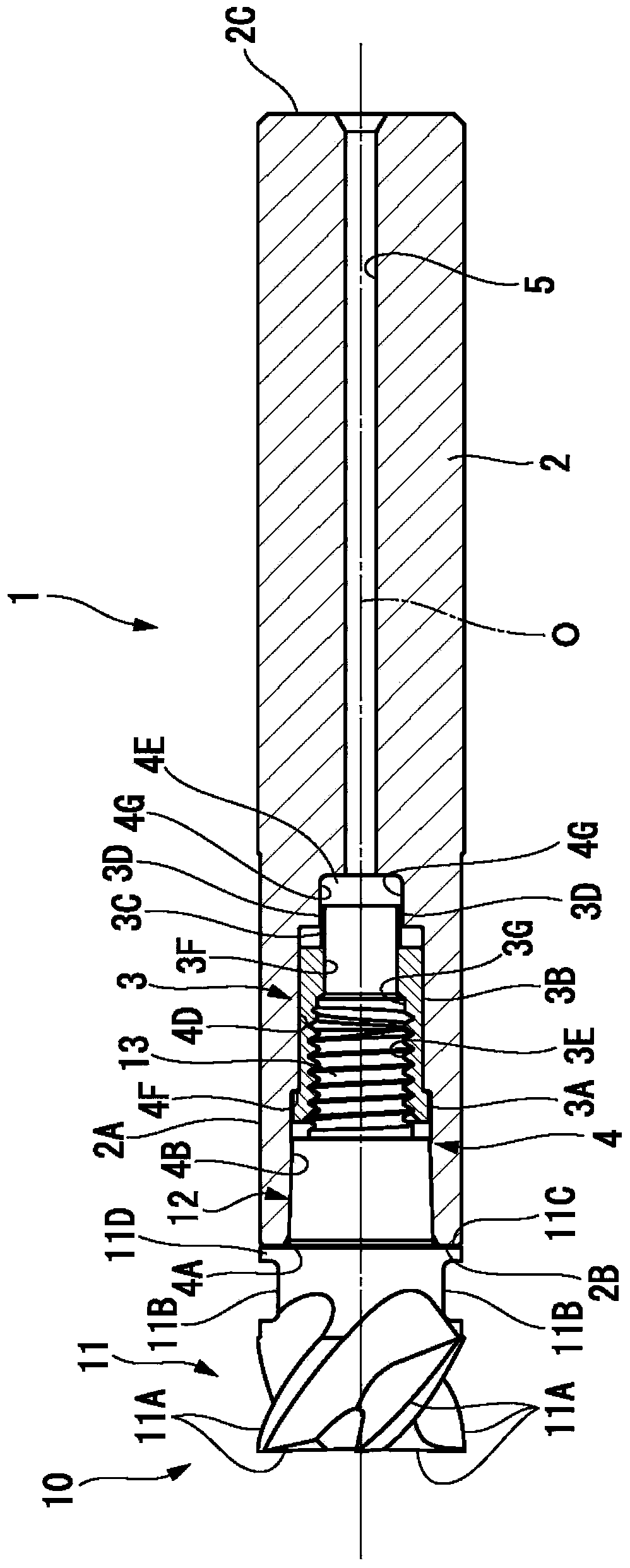
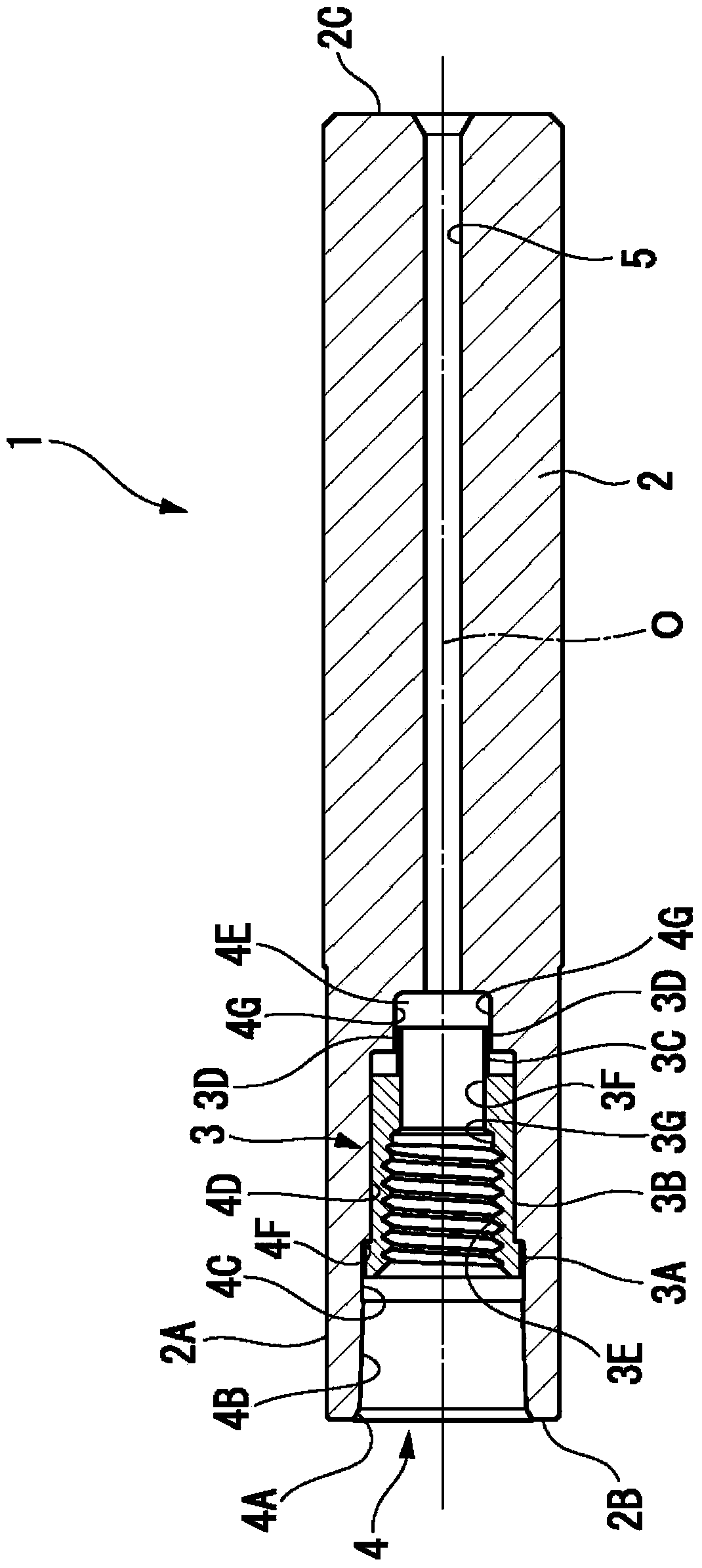
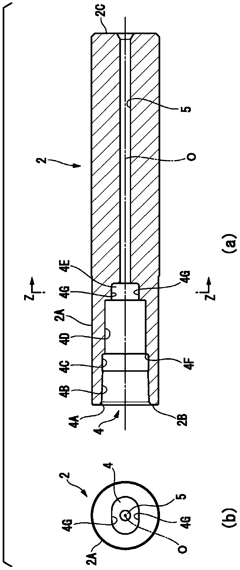
[0124]Next, the ratio d / D1 of the inner and outer diameters of the tool holder 1 and the expansion ratio of the outer diameter (D2-D1) / D1×100 (%) in the present invention will be described with examples. In this example, based on the head replaceable cutting tool (head replaceable end mill) of the above-mentioned embodiment, the holder 1 in the state before the mounting part 12 of the cutting head 10 is first fitted In the two head exchangeable cutting tools in which the outer diameter D1 of the front end of the holder main body 2 is 0.01 m (10 mm) and 0.02 m (20 mm), the inner diameter d of the opening side of the above-mentioned mounting hole 4 of the fitting portion 4B is The allowable torque with respect to the ratio d / D1 of the inner and outer diameters during the change is calculated in the following two cases, that is, as the minimum for cutting, the stress generated in the tool seat 1 is designed to be 100MPa (for example, as For light cutting), and as the upper limit ...


PUM

PropertyMeasurementUnit
Average particle sizeaaaaaaaaaa

Abstract

A holder (1) has a taper-shaped fitting section (4B) formed in a mounting hole (4), and a front end surface (2B) is set perpendicular to a centerline (O). A cutting head (10) has a taper-shaped mounting section (12) protruding from a rear end surface (11C) perpendicular to the centerline (O) of a cutting blade section (11). The cutting head (10) and the holder (1) are mounted to each other in such a manner that female and male threaded sections (3E, 13) are engaged with each other to thereby fit the mounting section (12) and the fitting section (4B) to each other and to thereby make the front end surface (2B) and the rear end surface (11C) in contact with each other. The inner / outer diameter ratio (d / D1) before the fitting, the inner / outer diameter ratio (d / D1) being the ratio between the inner diameter (d) of the fitting section (4B) and the outer diameter (D1) of the front end of the holder (1), is set to be in the range from 0.5 to 0.8, and the outer diameter expansion ratio ((D2 - D1) / D1 100 (%)) of the difference (D2-D1) between the outer diameter (D2) of the front end of the holder (1) after the fitting and the outer diameter (D1) to the outer diameter (D1) is set to be in the range from 0.022*d / D1-0.003 (%) to 0.33*d / D1-0.06 (%).

Description

technical field [0001] The present invention relates to an exchangeable head cutting tool in which an exchangeable cutting head having a blade portion is detachably attached to a holder for an exchangeable head cutting tool. Background technique [0002] As such a head replaceable cutting tool, Patent Document 1 describes a head replaceable end mill in which a blade portion is detachably fixed to a main body, and one end of the blade portion has a The cutting edge portion that is arranged around the axis and has a tapered shaft portion at the other end, the end diameter of the tapered shaft portion is smaller than the blade diameter of the blade portion, and its taper is 1 / 50 or less, the blade portion is tapered with the main body Fitted and fixed, the main body includes a joint part and a shank part, the joint part is formed of cemented carbide using WC with an average particle size of 3 microns or more, and constitutes a gradient that increases toward the shank side with ...

Claims


Application Information

Patent Timeline
IPC IPC(8): B23C5/10B23C5/22
CPCB23C5/10B23C2265/08B23C2265/32B23B31/1122B23C2240/32B23C2210/02B23C2210/03B23B31/11B23C5/109
Inventor 阿部太郎木村良彦畔上贵行
Owner MITSUBISHI MATERIALS CORP
Why Eureka
Try Eureka