
Method for calculating material removal rate for liquid magnetic grinding tool small hole finishing processing

A liquid magnetic and finishing technology, applied in computing, special data processing applications, instruments, etc., can solve problems such as the inability to achieve quantitative control and affect the development, promotion and application of special machine tools

Active Publication Date: 2014-06-04
TAIYUAN UNIV OF TECH
View PDF7 Cites 10 Cited by
  • Summary
  • Abstract
  • Description
  • Claims
  • Application Information

AI Technical Summary

Problems solved by technology

[0002] Modern industrial production puts forward higher and higher requirements on the surface quality of the inner wall of the hole. Although in recent years, researchers at home and abroad have proposed some non-traditional finishing technologies and composite finishing technologies. These technologies use electric energy, magnetic energy, Sound energy, light energy, chemical energy or the composite action of multiple processing methods complement each other to realize the finishing and processing of the workpiece, and have achieved good results in the precision finishing of some hole surfaces, but these Processing technology has its own optimal application range, and there are deficiencies or certain limitations in the finishing of small holes, especially shoulder holes, cross holes, special-shaped holes, etc., and it is difficult to meet the precision finishing requirements of modern manufacturing industries. Processing requirements, liquid magnetic abrasive finishing technology can complete the finishing of small holes, but because there is no quantitative material removal rate calculation model, quantitative control cannot be achieved, which affects the development of special machine tools and the popularization and application of this technology

Method used


Image

  • Method for calculating material removal rate for liquid magnetic grinding tool small hole finishing processing
  • Method for calculating material removal rate for liquid magnetic grinding tool small hole finishing processing
  • Method for calculating material removal rate for liquid magnetic grinding tool small hole finishing processing

Examples


Embodiment Construction

[0064] The above and other technical features and advantages of the present invention will be described in more detail below in conjunction with the accompanying drawings.

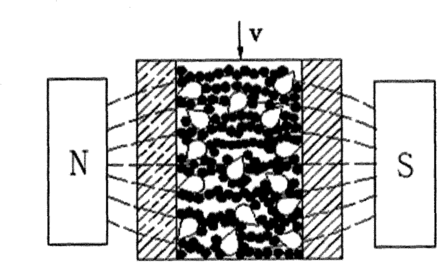
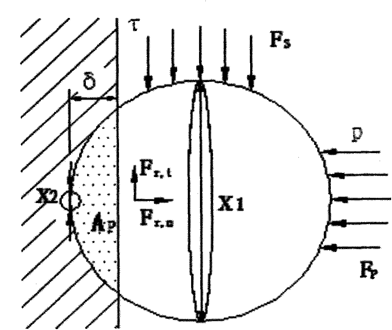
[0065] Guided by the theory of magneto-induced phase transition, the invention expounds the material removal mechanism of liquid magnetic grinding tool hole finishing from a microcosmic perspective. Using the "double edge circle radius" model to study the cutting model of a single abrasive particle, the mathematical expression of the material removal rate in the finishing process of small holes is obtained.

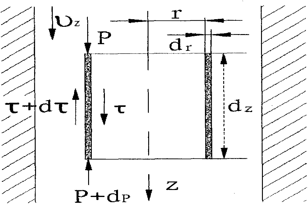
[0066] see figure 1 As shown, it is a mechanism diagram of liquid magnetic abrasive tool for small hole inner wall surface finishing of the present invention. Liquid magnetic abrasive tool is a new type of intelligent precision finishing abrasive based on the theory of magneto-induced phase transition. It consists of carrier liquid, magnetic Granules, abrasive particles and stabilizers. The magnetic...


PUM


Abstract

The invention relates to a method for calculating a material removal rate for liquid magnetic grinding tool small hole finishing processing. According to magneto-rheological features of a liquid magnetic grinding tool, a material removal mechanism of liquid magnetic grinding tool small hole finishing processing is explained from a microcosmic point of view. A double-blade circle radius model is adopted to serve as a cutting model of a single abrasive particle for research, a mathematical expression of the material removal rate of small hole finishing processing is deduced, theoretical analysis is carried out on influence factors of the mathematical expression, and accordingly it is concluded that the material removal rate of finishing processing is in direct proportion to the square of the diameter of the abrasive particle, shearing stress of the liquid magnetic grinding tool and fluid pressure, and is in inverse proportion to the yield limit of a workpiece material. In a certain range, removal efficiency of the material can be improved by increasing the diameter of abrasive particles, inlet pressure and current intensity, and quality of surfaces obtained after the surfaces are processed for a period of time is correspondingly improved.

Description

technical field [0001] The invention relates to the field of finishing processing, in particular to a calculation method for material removal rate of small hole finishing processing of a liquid magnetic abrasive tool. Background technique [0002] Modern industrial production puts forward higher and higher requirements on the surface quality of the inner wall of the hole. Although in recent years, researchers at home and abroad have proposed some non-traditional finishing technologies and composite finishing technologies. These technologies use electric energy, magnetic energy, Sound energy, light energy, chemical energy or the composite action of multiple processing methods complement each other to realize the finishing and processing of the workpiece, and have achieved good results in the precision finishing of some hole surfaces, but these Processing technology has its own optimal application range, and there are deficiencies or certain limitations in the finishing of sma...

Claims


Application Information

Patent Timeline
IPC IPC(8): B24B1/00G06F19/00
CPCB24B1/005
Inventor 孙桓五周钦
Owner TAIYUAN UNIV OF TECH
Learn More