Eureka AIR delivers breakthrough ideas for toughest innovation challenges, trusted by R&D personnel around the world.

A thick gold wire bonding method

A gold wire bonding and bonding technology, which is used in the manufacture of electrical components, electrical solid-state devices, semiconductor/solid-state devices, etc., can solve gold brittleness, reduce interconnect reliability, and reduce the sensitivity of signal processing, electrical performance indicators of microwave and millimeter wave modules. And other issues

Active Publication Date: 2016-08-17
CHINA ELECTRONIS TECH INSTR CO LTD
View PDF7 Cites 0 Cited by
  • Summary
  • Abstract
  • Description
  • Claims
  • Application Information

AI Technical Summary

Problems solved by technology

In the prior art, when the copper wire and the gold-plated microwave millimeter wave circuit substrate are soldered and interconnected, gold and tin easily form an intermetallic compound and cause "gold brittleness", thereby reducing the reliability of the interconnection; in addition, due to the "contact potential difference", the copper wire After interconnecting with the gold-plated pad of the circuit substrate, there is a contact potential difference at the interconnection interface, and the electrical performance index of the microwave and millimeter wave module and its sensitivity to signal processing are reduced

Method used


Image

  • A thick gold wire bonding method
  • A thick gold wire bonding method
  • A thick gold wire bonding method

Examples


Embodiment 1

[0027] Thick gold wire bonding among the present invention adopts thermocompression bonding mode, and its main technical scheme is as follows:

[0028] 1. Selection of bonding welding tools

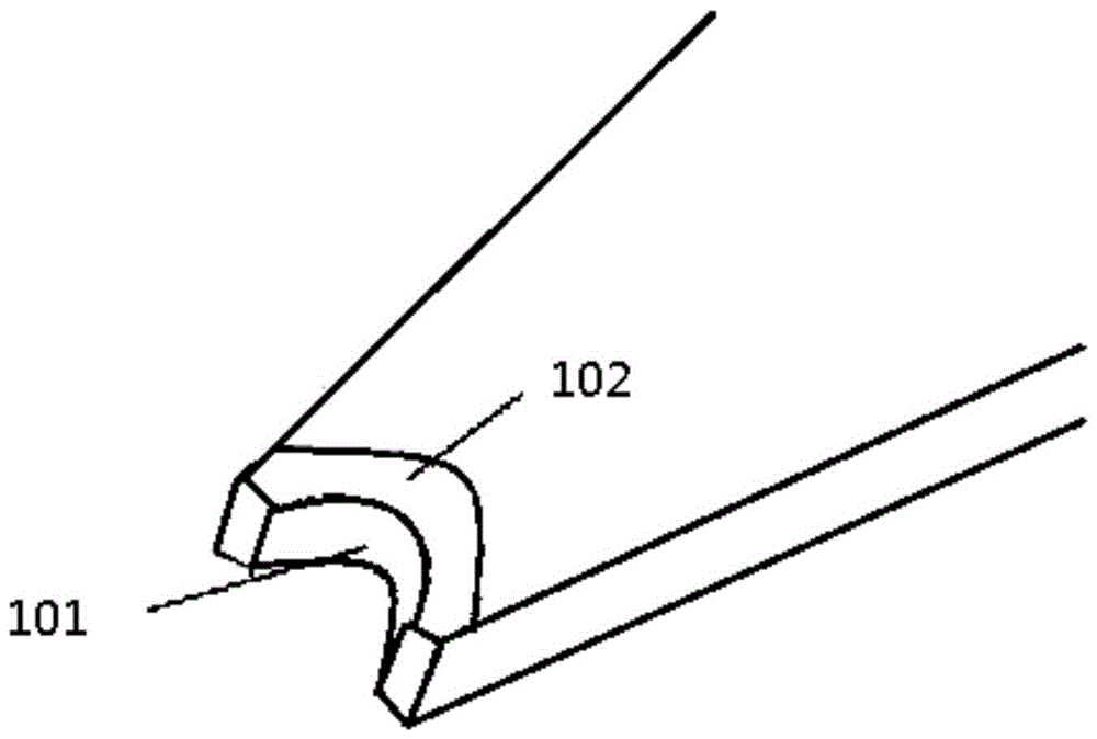
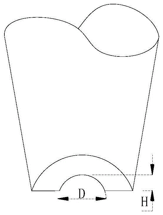
[0029] Such as figure 2 As shown, in order to facilitate the operation of limiting and applying pressure to the gold wire, the bonding end surface of the welding tool adopts a groove structure 101, and in order to ensure that the damage to the surface of the gold wire during the bonding process is minimized, the grooved type should be selected Soldering tools, and the groove edge should have a rounded structure 102, such as figure 2 Shown is a three-dimensional schematic diagram of the welding end face of the welding tool. figure 2 Among them, the groove structure 101 of the bonding end surface of the welding tool adopts a circular arc structure, the groove diameter D is 110%-120% of the diameter d of the bonded gold wire, and the groove depth H is 30%-40% of the diameter d of the bo...

Embodiment 2

[0038] On the basis of the foregoing embodiments, further, as Figure 2-Figure 8 Shown, a kind of coarse gold wire bonding method, wherein, comprises the following steps:

[0039] Step 1: Set the bonding end surface of the welding tool to adopt a groove structure 101, and the edge of the groove should have a rounded structure 102;

[0040] Step 2: place the processed gold wire 201 on the pad of the thin film circuit substrate;

[0041] Step 3: Place the thin film circuit substrate together with the gold wire 201 on a heating table at 150°C for heating, and at the same time turn on the bonding equipment, heat the soldering tool with a heating coil at a heating temperature of 150°C, and perform bonding after the heating is stable;

[0042] Step 4: Manual bonding is used during bonding, and pressure is applied for bonding to deform the gold wire to a predetermined range.

[0043] The groove structure in the step 1 is an arc structure.

[0044] The groove diameter of the groove...


PUM


Abstract

The invention provides a coarse gold wire bonding method. The method comprises the steps that a groove-shaped structure is used for a bonding end face of a soldering set, and a fillet-shaped structure is on the groove edge; a gold wire with processed length is placed on a pad of a film circuit substrate; the film circuit substrate and the gold wire are placed together on a heating bench at the temperature of 150 DEG C for heating, and at the same time a bonding device is turned on; the soldering set is heated by a heating coil, and bonding is carried out after stabilized heating, wherein the heating temperature is 150 DEG C; and a manual bonding mode is used when bonding is carried out, and pressure is applied for bonding, so that the gold wire deforms to a predetermined range. According to the scheme, the problem of reduced reliability, which is caused by the phenomenon of 'gold crisp' when tin soldering interconnection is carried out on a copper wire and the gold plated film circuit substrate, is solved; and the impact of 'contact potential difference' caused by the tin soldering interconnection of the copper wire and the gold plated film circuit substrate on an electrical performance index is reduced.

Description

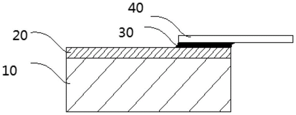
technical field [0001] The invention belongs to the technical field of thick gold wire bonding, and in particular relates to a thick gold wire bonding method. Background technique [0002] In some applications of microwave and millimeter wave modules, it is necessary to use metal wires with a diameter of more than 100 microns to realize signal communication between the internal and external circuits of the module. On the one hand, thick metal wires have high strength and are suitable for interconnection between internal and external circuits of the module. ; On the other hand, thick wire has a lower series resistance and is suitable for high power or high current situations. [0003] At present, thick copper wire soldering interconnection is mostly used, and the interconnection schematic diagram is as follows figure 1 As shown, 10 is a dielectric substrate, 20 is a gold-plated conduction band, 30 is solder, and 40 is a red copper wire. In the prior art, when the copper wir...

Claims


Application Information

Patent Timeline
Patent Type & Authority Patents(China)
IPC IPC(8): H01L21/60
CPCH01L24/85H01L2224/45144H01L2224/45147H01L2224/85H01L2224/85203H01L2924/00H01L2924/00014H01L2924/00012H01L2924/00015
Inventor 王斌李红伟刘金现
Owner CHINA ELECTRONIS TECH INSTR CO LTD
Why Eureka
Eureka Blog
Learn More