
Power tube drive method and circuit, and direct-current solid power controller

A solid-state power and drive circuit technology, applied in electrical components, electronic switches, pulse technology, etc., can solve the problems of unstable switching speed, complex implementation of technical solutions, and large impact, and achieve easy integration, simple and reliable drive circuits. , to achieve the effect of low cost

Inactive Publication Date: 2014-05-14
NANJING UNIV OF AERONAUTICS & ASTRONAUTICS
View PDF8 Cites 26 Cited by
  • Summary
  • Abstract
  • Description
  • Claims
  • Application Information

AI Technical Summary

Problems solved by technology

The advantage of this solution is that it is relatively simple to implement, but the disadvantage is that the switching speed of the power tube is not constant during the switching process. The control effect of the switching speed is greatly affected by the parameters of the power tube and the ambient temperature, and it is difficult to adjust the parameters.
In the Chinese invention patent application with the publication number CN102545855A, a closed-loop drive circuit technical solution is proposed, which overcomes the problem of the "slow on and slow off" drive circuit based on the RC network, but its disadvantage is that the realization of the technical solution is relatively complicated and must be adopted High-Bandwidth High-Speed ​​Operational Amplifiers

Method used


Image

  • Power tube drive method and circuit, and direct-current solid power controller
  • Power tube drive method and circuit, and direct-current solid power controller
  • Power tube drive method and circuit, and direct-current solid power controller

Examples


Embodiment Construction

[0021] Describe the present invention in detail below in conjunction with accompanying drawing.

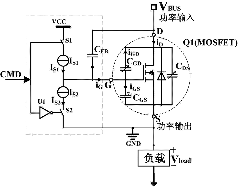
[0022] Such as figure 1 Shown in the rectangular dotted line frame is the DC solid-state power controller power tube drive circuit proposed by the present invention, including the first switch S1, the first constant current source I S1 , the second switch S2, the second constant current source I S2 , NOT gate U1 and feedback capacitor C FB . The first switch S1 and the first constant current source I S1 The first channel is formed in series, the second switch S2 and the second constant current source I S2 Connected in series to form the second channel. The first channel and the second channel are connected in series between the positive pole VCC of the power supply of the driving circuit and the reference ground GND, the connection point of the first channel and the second channel is connected to the gate of the power transistor Q1, and the reference ground GND of the driving...


PUM


Abstract

The invention discloses a power tube drive method and a power tube drive circuit. The power tube drive method and the power tube drive circuit are applied to a direct-current solid power controller. The power tube drive circuit comprises a charging and discharging constant current source, a corresponding control switch, a not gate, and a feedback capacitor connected between the grid electrode and the drain electrode of a power tube in a bridging mode. In the turning on and turning off process of the direct-current solid power controller, the constant current source is controlled to charge and discharge the feedback capacitor, and the feedback capacitor feeds voltages of the drain electrode and the source electrode of the power tube back to the power grid electrode. The invention further discloses the direct-current solid power controller comprising the power drive circuit. According to the power tube drive method and circuit, and the direct-current solid power controller, the power tube can be turned on and turned off at a low and constant switching speed, load voltages are increased or decreased in a linear mode, and the rate of increasing and decreasing is adjustable. The power tube drive method and the power tube drive circuit are suitable for conventional Si MOSFETs and IGBTs, and also are suitable for Sic and GaN field control type power tubes like JFETs, MOSFETs and IGBTs. The drive circuit is simple and reliable, easy to integrate, and low in cost.

Description

technical field [0001] The invention relates to a power tube driving method and circuit applied to a DC solid-state power controller, and belongs to the fields of power electronics technology and electrotechnical technology. Background technique [0002] Solid State Power Controller (SSPC for short) is a solid-state power distribution device with a semiconductor power tube as the core, which integrates the switching function of the relay and the protection function of the circuit breaker. SSPC has the advantages of no contact, no arc, no noise, fast response, low electromagnetic interference, long life, high reliability, and easy computer remote control. It is being widely used in aircraft, tanks, ships, and civil distribution networks. [0003] The DC SSPC is used in the DC power system to realize the connection or disconnection of the circuit, and complete the circuit fault protection and isolation. In order to improve the load compatibility of DC SSPC, reduce the inrush ...

Claims


Application Information

Patent Timeline
Patent Type & Authority Applications(China)
IPC IPC(8): H03K17/567
Inventor 王莉阮立刚
Owner NANJING UNIV OF AERONAUTICS & ASTRONAUTICS
Learn More