
Chip packaging method and packaging structure

A technology of chip packaging and packaging structure, which is applied in the direction of electrical components, electrical solid devices, semiconductor/solid device manufacturing, etc., to achieve the effects of improving reliability, improving electrical connection performance, and improving interface quality

Active Publication Date: 2014-05-07
CHINA WAFER LEVEL CSP
View PDF5 Cites 4 Cited by
  • Summary
  • Abstract
  • Description
  • Claims
  • Application Information

AI Technical Summary

Problems solved by technology

[0008] The reliability of the packaging structure formed by the existing chip packaging method needs to be further improved

Method used


Image

  • Chip packaging method and packaging structure
  • Chip packaging method and packaging structure
  • Chip packaging method and packaging structure

Examples


Embodiment Construction

[0034] As mentioned in the background art, the reliability of the packaging structure formed by the existing chip packaging method is low.

[0035] On the one hand, because the thickness of the solder resist layer filled in the groove is relatively large, during the process of thermal curing of the solder resist layer, due to the difference in thermal expansion coefficient between the solder resist layer and the wafer, greater stress will be generated , and passed to the customer layer, generating greater stress in the customer layer; subsequent reflow soldering process is used to form solder balls, and the high temperature in the reflow soldering process will also cause stress in the customer layer. Since the client layer is a complete whole before wafer dicing, the stress in the client layer cannot be completely released. When the chip is cut, the customer layer is no longer a whole. At this time, the thermal curing of the solder mask layer, the residual stress in the solder...


PUM


Abstract

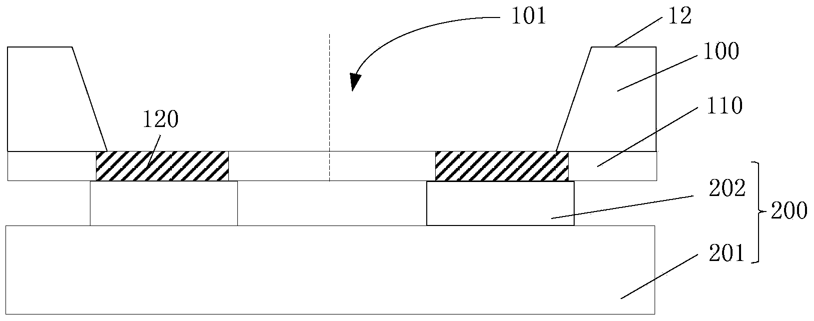
Provided are a chip packaging method and a packaging structure. The chip packaging method includes the steps of providing a substrate, wherein the substrate comprises a substrate body and a client layer on the surface of the substrate body, the surface of the client layer is a first surface, the surface, opposite to the first surface, of the substrate body is a second surface, and multiple welding pads are formed in the client layer; etching the second surface of the substrate to form a first groove, wherein the welding pads and a part of the surface of the client layer are exposed from the bottom of the first groove; forming an insulating layer on the surface of the inner wall of the first groove; forming a second groove which sequentially penetrates through the adjacent welding pads and the client layer between the adjacent welding pads in the arrangement direction of the welding pads; forming wiring metal layers on the surface of the first groove, the surface of the second groove and the surface of the insulating layer; forming solder mask layers on the surfaces of the wiring metal layers, wherein openings are formed in the solder mask layers, and partial surfaces of the wiring metal layers are exposed from the openings; forming solder balls located on the surfaces of the wiring metal layers in the openings. The chip packaging method can improve reliability of the packaging structure.

Description

technical field [0001] The invention relates to the technical field of semiconductors, in particular to a chip packaging method and packaging structure. Background technique [0002] Wafer Level Chip Size Packaging (WLCSP) technology is a technology that performs packaging and testing on the entire wafer and then cuts it to obtain a single finished chip. The size of the packaged chip is the same as that of the bare chip. Wafer-level chip-scale packaging technology has changed traditional packages such as ceramic leadless chip carrier (Ceramic Leadless Chip Carrier), organic leadless chip carrier (Organic Leadless Chip Carrier) and digital camera module mode, and complies with the market demand for microelectronics. Products are increasingly light, small, short, thin and low-cost requirements. The size of the chip packaged by the wafer-level chip size packaging technology has reached a high degree of miniaturization, and the cost of the chip is significantly reduced with the...

Claims


Application Information

Patent Timeline
Patent Type & Authority Applications(China)
IPC IPC(8): H01L21/60H01L21/56H01L23/488H01L23/31
CPCH01L2224/10H01L21/4853H01L23/49811H01L23/49838
Inventor 王之奇杨莹王蔚
Owner CHINA WAFER LEVEL CSP
Learn More