Surface pressure distribution sensor

Inactive Publication Date: 2005-03-08
ALPS ALPINE CO LTD
View PDF6 Cites 60 Cited by
  • Summary
  • Abstract
  • Description
  • Claims
  • Application Information

AI Technical Summary

Benefits of technology

Accordingly, it is an object of the present invention to provide a simple and low-cost surface pressure distribution sensor capable of stable and high-precision detection of a pressure distribution for a long period of time.
This surface pressure distribution sensor allows for high-precision detection of small irregularities, that is, small variations of the electrostatic capacitance. As the distance between the intersections of the row lines and the column lines varies depending upon the irregularities, the electrostatic capacitance also varies. The variations in the electrostatic capacitance are detected. The surface pressure distribution sensor can be manufactured at low cost with a simple structure.
The substrates may be formed of a single flexible film substrate. This flexible film substrate having the row lines and the column lines may be folded at a predetermined position so that the row lines and the column lines intersect with each other. Therefore, the surface pressure distribution sensor can be manufactured at lower cost with a simpler structure.
The flexible film substrate may be made of a resin having different thermal shrinkages in the first and second directions. If a tensile stress is caused by the row or column lines, the row lines and the column lines may be formed so as to extend in the higher-thermal-shrinkage direction. If a compressive stress is caused by the row or column lines, the row lines and the column lines may be formed so as to extend in the lower-thermal-shrinkage direction. This prevents disconnection of the row and column lines that can be caused by a film stress in the flexible film substrate.
Preferably, at least either the row lines or the column lines are coated with an insulating film, thus ensuring an electrostatic capacitance at the intersections of the row lines and the column lines.
The flexible film substrate may be made of a resin having different thermal shrinkages in the first and the second directions. If a tensile stress is caused by the row or column lines and the insulating film, the row lines and the column lines may be formed so as to extend in the higher-thermal-shrinkage direction. If a compressive stress is caused by the row or column lines and the insulating film, the row lines and the column lines may be formed so as to extend in the lower-thermal-shrinkage direction. This prevents disconnection of the row and column lines that can be caused by a film stress in the flexible film substrate.

Problems solved by technology

Such a surface pressure distribution sensor of the related art includes a semiconductor substrate, but semiconductor substrates are generally expensive.
In particular, when the surface pressure distribution sensor is used as a fingerprint detection sensor, the expensive semiconductor substrate must have an area large enough to be contacted with the finger, thus increasing the production cost.
However, in the surface pressure distribution sensor of the related art, it is difficult to maintain the contact area between the exposed portion of the semiconductor switching devices and the conductive coating clean for a long period of time.

Method used


Image

  • Surface pressure distribution sensor
  • Surface pressure distribution sensor
  • Surface pressure distribution sensor

Examples


Embodiment Construction

A surface pressure distribution sensor according to the present invention will be described hereinbelow.

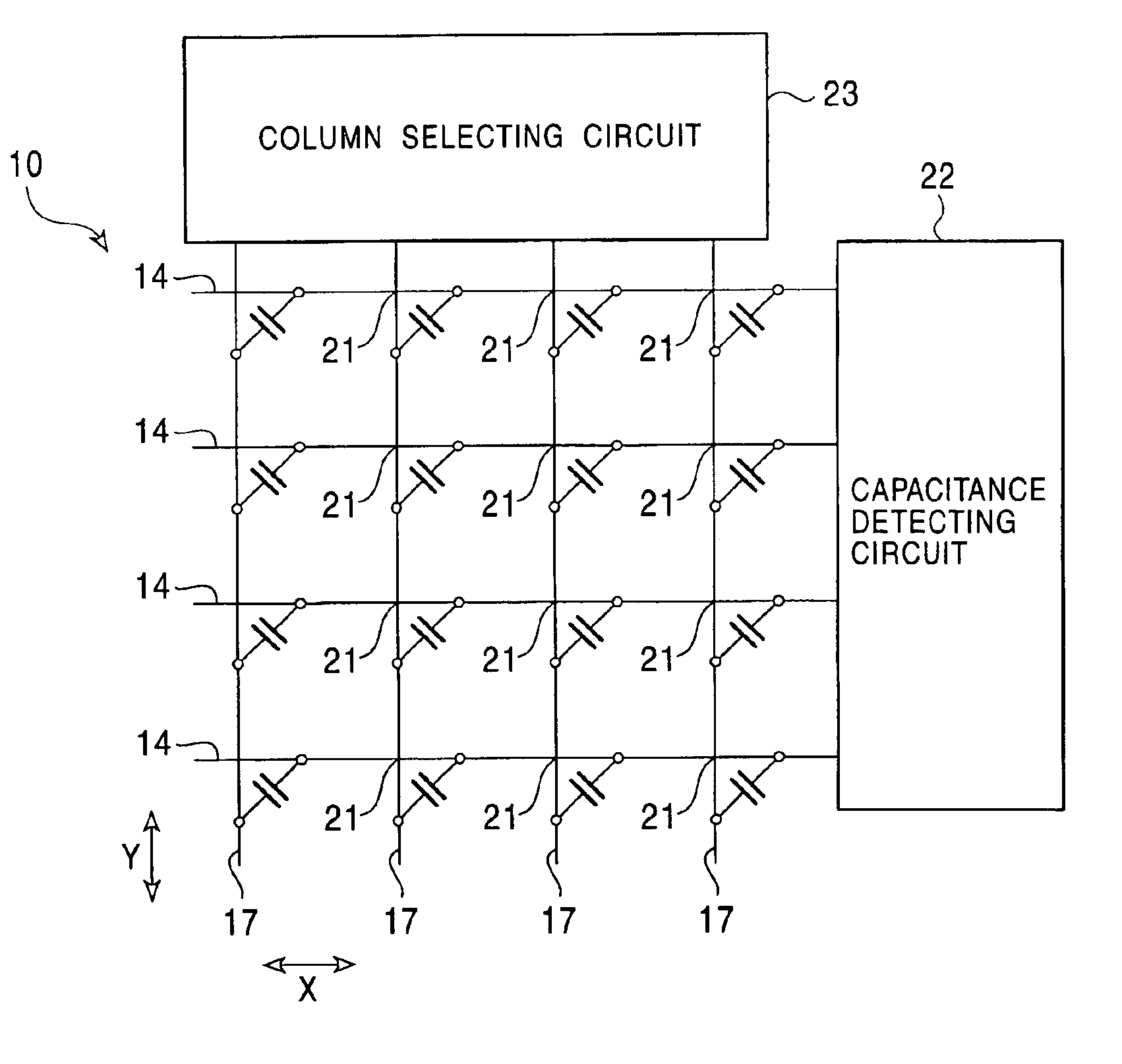
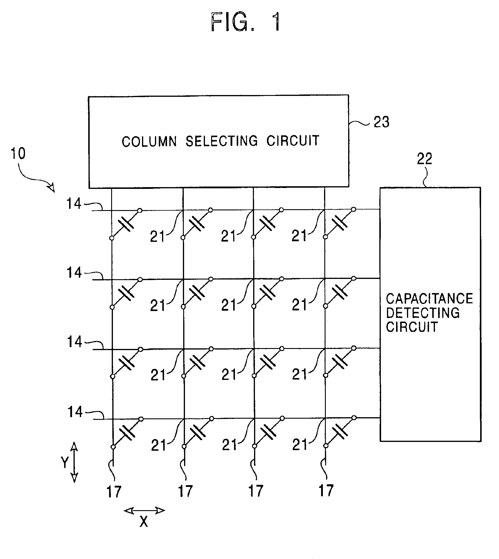
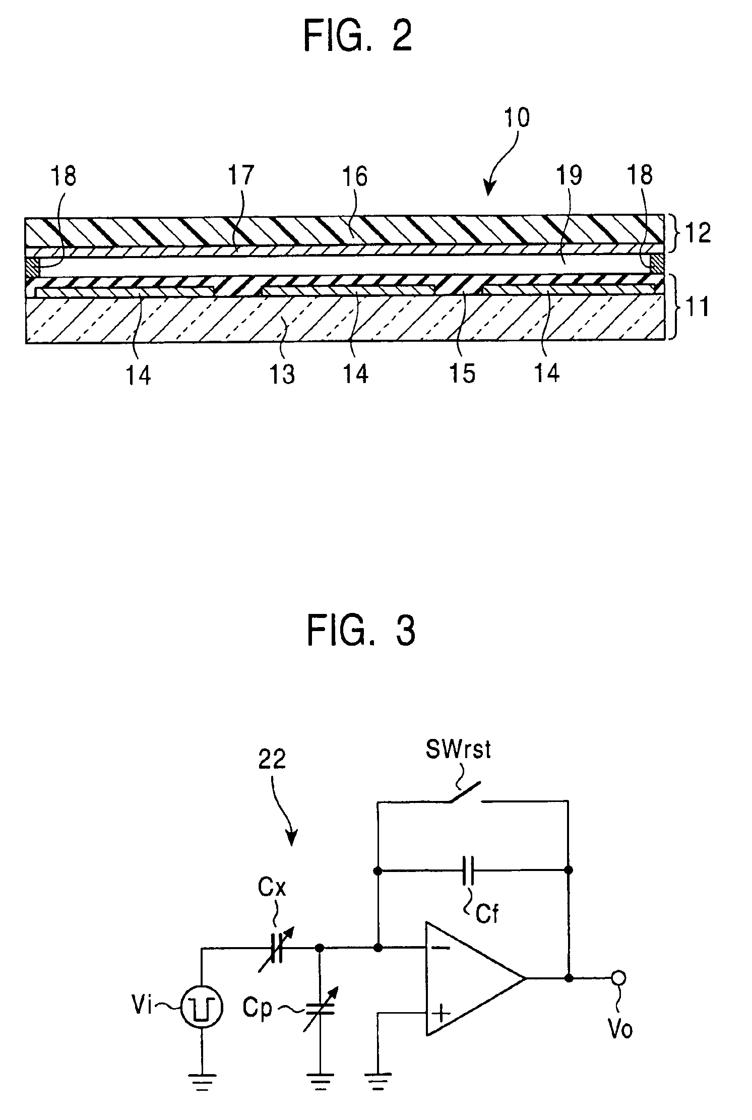
FIG. 1 is an equivalent circuit diagram of a surface pressure distribution sensor 10 according to a representative embodiment of the present invention, and FIG. 2 is a cross-sectional view of the main portion of the surface pressure distribution sensor 10 in an enlarged form. The surface pressure distribution sensor 10 includes a row-line portion 11 and a column-line portion 12 that face each other with a certain spacing therebetween by a spacer 18.

The row-line portion 11 includes a glass substrate 13, multiple row lines 14 formed on the glass substrate 13 so as to extend in parallel to each other in a first direction X, and an insulating film 15 that covers the row lines 14. Each of the row lines 14 is formed of, for example, an Al film of 0.1 μm thickness. For example, 200 row lines 14 are formed on the glass substrate 13 with 50 μm pitches therebetween. The insulating film 15 m...


PUM


Abstract

A surface pressure distribution sensor includes a row-line portion and a column-line portion that face each other with a certain spacing therebetween by a spacer. The row-line portion includes a glass substrate, multiple row lines formed on the glass substrate so as to extend in parallel to each other in a first direction, and an insulating film that covers the row lines. The column-line portion includes a flexible film and multiple column lines formed on the flexible film so as to extend in parallel to each other in a second direction orthogonal to the first direction.

Description

BACKGROUND OF THE INVENTION1. Field of the InventionThe present invention relates to a surface pressure distribution sensor for detecting small irregularities of an object to be sensed.2. Description of the Related ArtA surface pressure distribution sensor for detecting small irregularities in a surface of an object brought into contact with the sensor surface, as a pressure distribution, is described in, for example, Japanese Examined Patent Application Publication No. 7-58234 (corresponding to U.S. Pat. No. 5,400,662), showing a sensor for detecting the configuration of a coarse surface as data values.As shown in, for example, FIG. 11, such a surface pressure distribution sensor includes a matrix of semiconductor switching devices 101, and electrodes 102 each connected with one end of each of the semiconductor switching devices 101. A flexible film coated with a conductor is formed so as to face electrodes on the opposing side of a semiconductor substrate with a certain spacing th...

Claims


Application Information

Patent Timeline
IPC IPC(8): G06F3/033G06K9/00G01L5/00G01L1/14G06F3/041G06T1/00H01L29/84
CPCA61B5/1172G06K9/0002G06F3/0414G01L1/146G06V40/1306A46B11/0031A46B5/0095A46B11/0062A46B2200/1066
Inventor KAWAHATA, KEN
Owner ALPS ALPINE CO LTD
Why Eureka
Try Eureka