
System and method for controlling electronic equipment by knock

A technology for electronic equipment control and electronic equipment, which is applied in electrical digital data processing, input/output process of data processing, input/output of user/computer interaction, etc. Cost and other issues, to achieve the effect of reducing costs, easy operation, and achieving waterproofing

Inactive Publication Date: 2014-04-16
张燕
View PDF5 Cites 15 Cited by
  • Summary
  • Abstract
  • Description
  • Claims
  • Application Information

AI Technical Summary

Problems solved by technology

[0003] However, the above form 1 has the following disadvantages: a. Physical buttons are required on the device. For terminal devices, the size is usually very small, and there is not enough space to place the buttons. Even if there are buttons, the buttons are usually very small and inconvenient for users to operate
e. Due to the existence of the button, there is inevitably a gap between the button and the device, making the device unable to effectively waterproof, and waterproof is also very important for terminal equipment
The above form 2 has the following disadvantages: a. The device needs to provide a touch screen. For terminal devices, the size is usually very small, and the size of the touch screen allowed to be used is limited, making it difficult for the user to precisely locate the function control. User operation is not easy
b. The high price of the touch screen will greatly increase the cost of the equipment and affect the sales competitiveness of the equipment
c. The power consumption of the touch screen is relatively high, and the battery capacity of the terminal device is limited, which will reduce the continuous use time of the user and affect the user experience
In addition, the user needs to charge frequently, which indirectly reduces the life of the battery and ultimately affects the service life of the device.

Method used


Image

  • System and method for controlling electronic equipment by knock
  • System and method for controlling electronic equipment by knock

Examples


Embodiment Construction

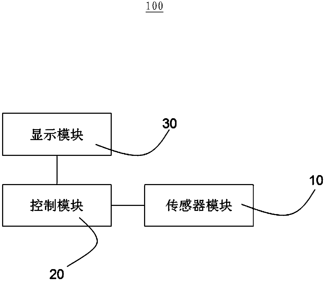
[0012] Such as figure 1 As shown, the present invention provides a system 100 for controlling an electronic device through tapping, where the electronic device is, for example, a sports tracker or a pedometer. A fitness tracker or pedometer is a wearable device with built-in sensors. They are usually worn on the user's waist, arms, wrists and other body parts, or hung on pockets, shoes and other objects that can move synchronously with the human body. The sports tracker can accurately record the time, distance, speed and altitude when the user is running, cycling, walking or sitting in other sports. The pedometer calculates calories by counting the number of steps, distance, speed, time and other data. Or calorie consumption, a tool to control the amount of exercise and prevent insufficient or excessive exercise. The system 100 for controlling an electronic device by tapping includes a sensor module 10 , a control module 20 connected to the sensor module 10 , and a display m...


PUM


Abstract

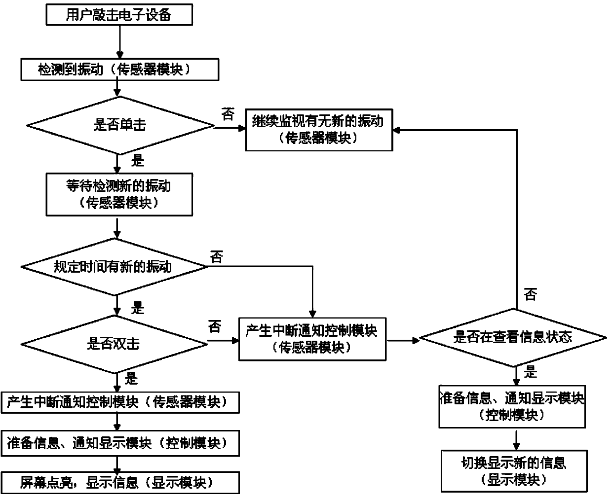
The invention provides a system and method for controlling electronic equipment by knock. The system comprises a sensor module, a control module connected to the sensor module, and a display module connected to the control module. The sensor module is used for detecting single clicks, double clicks or continuous single knocks at any positions on the surface of an electronic device and generating corresponding knock parameters; the control module is used for judging whether valid single clicks, double clocks or continuous single knocks on the surface of the electronic device occur or not according to the knock parameters and executing corresponding device management actions according to judging results; the display module is used for displaying corresponding information according to the device management actions. The electronic equipment is controlled through the sensor module and the control module, neither setting physical keys nor controlling via a touch screen is required, the size can be reduced, waterproofing is easy to achieve, the cost is reduced, and operation is facilitated.

Description

technical field [0001] The present invention relates to a system and a method for controlling an electronic device, in particular to a system and a method for controlling an electronic device by tapping. Background technique [0002] Portable devices and wearable devices such as exercise status trackers and pedometers are becoming more and more popular. People hope that such devices should be miniaturized, intelligent, and easy to operate. In terms of device control form, the existing technology mainly includes the following two forms: 1. Provide physical buttons on the device, and the user controls the device by operating the physical buttons to select and control functions; 2. Provide a touch screen on the device, The user controls the device through the touch screen to select and control functions. [0003] However, the above form 1 has the following disadvantages: a. Physical buttons are required on the device. For terminal devices, the volume is usually very small, and...

Claims


Application Information

Patent Timeline
IPC IPC(8): G06F3/01G06F3/0346
Inventor 张燕
Owner 张燕
Learn More