Photoresist Wall Forming Method

A molding method and photoresist technology, applied in optics, optomechanical equipment, instruments, etc., can solve the problems of strong water absorption, delamination of photoresist walls, low stiffness of photoresist materials, etc., and achieve high strength and low CTE. , reduce the effect of delamination and detachment

Active Publication Date: 2017-09-29
北京中科微知识产权服务有限公司
View PDF6 Cites 0 Cited by
  • Summary
  • Abstract
  • Description
  • Claims
  • Application Information

AI Technical Summary

Problems solved by technology

The main problem of using photoresist to make the photoresist wall structure is that the photoresist material itself has small rigidity, large thermal expansion coefficient, and strong water absorption. In the subsequent baking process and reliability test, photoresist wall delamination or delamination from the glass often occurs. The phenomenon of shedding seriously affects product quality and service life
At the same time, the residue after exposure and development can easily lead to reliability problems of the sensor

Method used


Image

  • Photoresist Wall Forming Method
  • Photoresist Wall Forming Method
  • Photoresist Wall Forming Method

Examples


Embodiment Construction

[0020] The present invention will be further described below in conjunction with drawings and embodiments.

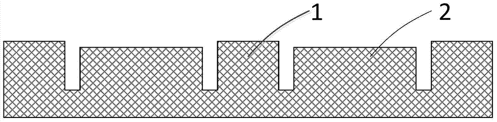
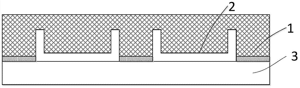
[0021] 1. Use injection molding technology to form a flat plate, such as figure 2 As shown, the front of the flat plate has a first boss 1 and a second boss 2, the first boss 1 is grid-like, and each grid has a second boss 2, and the first boss 1 It is separated from the second boss 2 by a groove, the height of the first boss 1 is greater than that of the second boss 2, and the height difference is greater than 20 microns. The flatness of the surface of the first boss 1 is less than 5 microns. The flat panel can be encapsulated by epoxy resin, polytetrafluoroethylene, phenolic resin, benzoxazine resin, cyanate resin, polyimide, bismaleimide, polyphenylene ether, polyetheretherketone, etc. and its modified materials. Taking glass fiber-reinforced epoxy resin as an example, the maximum temperature it can withstand after curing exceeds 260 degrees Celsius, which exceed...


PUM

PropertyMeasurementUnit
transmittivityaaaaaaaaaa

Abstract

The invention provides a method for forming a photoresist wall, which uses injection molding technology to form a flat plate, the front of the flat plate has a first boss and a second boss, and the first boss and the second boss are separated by a groove ; roll glue on the front of the plate and press it with the first substrate, so that the first boss sticks on the first substrate; grind and thin the back of the plate until the first boss and the second boss The bottom of the stage is separated; the second boss remaining on the first substrate is removed, and the residue on the first boss is cleaned to form a photoresist wall structure. The advantage of the present invention is that: the photoresist wall structure in the present invention is formed separately, and compared with the traditional photoresist photolithography method, the probability of defective devices caused by pollution during the process of forming the photoresist wall can be greatly reduced. The materials used for injection molding have properties such as high stiffness, low CTE and low moisture absorption, which can improve the structural strength of the photoresist wall mask and effectively reduce reliability problems such as delamination and detachment.

Description

technical field [0001] The invention relates to a method for forming a photoresist wall, which belongs to the technical field of semiconductor manufacturing. Background technique [0002] The photoresist wall photomask currently used in image sensors is made by spin-coating photoresist on a glass wafer, and forming a regularly arranged photoresist wall structure on the photoresist through exposure and development, such as figure 1 shown. The main problem of using photoresist to make the photoresist wall structure is that the photoresist material itself has small rigidity, large thermal expansion coefficient, and strong water absorption. In the subsequent baking process and reliability test, photoresist wall delamination or delamination from the glass often occurs. The phenomenon of shedding seriously affects product quality and service life. At the same time, the residue after exposure and development can easily lead to reliability problems of the sensor. As image sensors...

Claims


Application Information

Patent Timeline
Patent Type & Authority Patents(China)
IPC IPC(8): G03F7/00
Inventor 徐成于大全李昭强
Owner 北京中科微知识产权服务有限公司
Why Eureka
Try Eureka