Method for forming Llight resistance wall molding method by adopting silicon mold

A molding method and technology of silicon molds, which are applied in the direction of photo-plate making process of originals for photomechanical processing, optics, pattern surface, etc., can solve the problem of affecting product quality and service life, low rigidity of photoresist materials, and reliable sensors Sexual problems and other problems, to achieve the effect of improving strength, reducing delamination and detachment, and low moisture absorption

Inactive Publication Date: 2014-04-16
NAT CENT FOR ADVANCED PACKAGING
View PDF3 Cites 3 Cited by
  • Summary
  • Abstract
  • Description
  • Claims
  • Application Information

AI Technical Summary

Problems solved by technology

The main problem of using photoresist to make the photoresist wall structure is that the photoresist material itself has small rigidity, large thermal expansion coefficient, and strong water absorption. In the subsequent baking process and reliability test, photoresist wall delamination or delamination from the glass often occurs. The phenomenon of shedding seriously affects product quality and service life
At the same time, the residue after exposure and development can easily lead to reliability problems of the sensor

Method used


Image

  • Method for forming Llight resistance wall molding method by adopting silicon mold
  • Method for forming Llight resistance wall molding method by adopting silicon mold
  • Method for forming Llight resistance wall molding method by adopting silicon mold

Examples


Embodiment Construction

[0024] The present invention will be further described below in conjunction with drawings and embodiments.

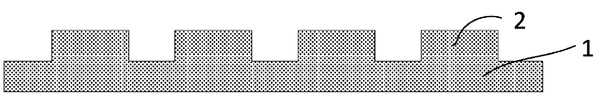
[0025] 1. The present invention first uses wet etching, dry etching, laser cutting or wire cutting to make silicon mold 1, such as figure 2 As shown, the front side of the silicon mold 1 has an array of bosses 2, and the grid-shaped grooves between the bosses form a mold cavity; the depth of the grooves is 50 to 150 microns.

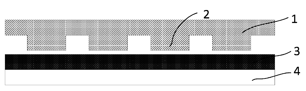
[0026] 2. If image 3 As shown, the thermoplastic material 3 is coated on the first substrate 4 with a thickness of 20 to 100 microns, and heated to the melting temperature of the material, and the front side of the silicon mold 1 is pressed on the first substrate with the thermoplastic material 3 by molding. 4; or the thermoplastic material 3 is filled between the front of the silicon mold 1 and the first substrate 4 by means of pressure injection. The thermoplastic material 3 can be epoxy resin, polytetrafluoroethylene, phenolic resin, benzox...


PUM

PropertyMeasurementUnit
depthaaaaaaaaaa
transmittivityaaaaaaaaaa

Abstract

The invention provides a method for forming a light resistance wall molding method by adopting a silicon mold. The method comprises the following steps: the silicon mold, the front side of which the front side is provided with boss arrays, is manufactured, and mold cavities are formed by latticed grooves among the bosses; the front side of the silicon mold is pressed on a first baseplate with thermoplastic material through a mould pressing method; or the gap between the front side of the silicon mold and the first baseplate is fully filled with the thermoplastic material through a pressure casting method; the silicon mold is separated from the first baseplate after the mold cavities are fully filled with the thermoplastic material; a light resistance wall structure is formed on the first baseplate; the first baseplate is cleaned to removeso that residues on the first baseplate and the light resistance wall structure are removed. The silicon mold can be manufactured through the method of wet etching, dry etching, laser cutting or line cutting; the molding method has the advantages that the silicon is adopted to manufacture the mold, so that the cost of the mold manufacturing is reduced greatly; meanwhile, the etching method can be used for manufacturing the light resistance wall structures with different patterns conveniently and flexibly; compared with the conventional photoetching technology, the molding method adopts the silicon mold, so that more flexible choices on the requirements of materials of the light resistance wall are achieved.

Description

technical field [0001] The invention relates to a method for forming a photoresist wall using a silicon mold, and belongs to the technical field of semiconductor manufacturing. Background technique [0002] The photoresist wall photomask currently used in image sensors is made by spin-coating photoresist on a glass wafer, and forming a regularly arranged photoresist wall structure on the photoresist through exposure and development, such as figure 1 shown. The main problem of using photoresist to make the photoresist wall structure is that the photoresist material itself has small rigidity, large thermal expansion coefficient, and strong water absorption. In the subsequent baking process and reliability test, photoresist wall delamination or delamination from the glass often occurs. The phenomenon of shedding seriously affects product quality and service life. At the same time, the residue after exposure and development can easily lead to reliability problems of the sensor...

Claims


Application Information

Patent Timeline
Patent Type & Authority Applications(China)
IPC IPC(8): G03F1/68G03F1/80H01L27/146
Inventor 徐成于大全李昭强
Owner NAT CENT FOR ADVANCED PACKAGING
Why Eureka
Try Eureka