Falling film plate and shell heat exchanger
A heat exchanger and falling film technology, which is applied in the field of new heat exchangers, can solve the problems of high material cost, large volume and large amount of pipe materials.
- Summary
- Abstract
- Description
- Claims
- Application Information
AI Technical Summary
Problems solved by technology
Method used
Image

Examples
Embodiment 1
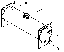
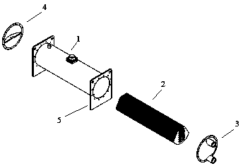
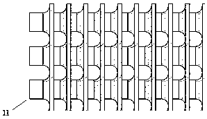
[0015] Embodiment one, such as Figure 1 to Figure 4 As shown, the falling film plate and shell heat exchanger of the present invention includes a shell 1, a plate core 2, an end cover 3 and an end cover 4, and a shell side inlet 6 and a shell side outlet 7 are arranged on the shell 1. Cover 3 has pipe side inlet 8, pipe side outlet 9. The plate core 2 is composed of several identical plates 10, each plate has holes and protruding edges 11, which form a closed internal flow channel after combination, while the outside is a heat transfer surface formed by the plates. When in use, one fluid enters from the inlet 8 on the tube side, flows through the inner flow channel of the plate core, and then flows out from the outlet 9 on the tube side; the other fluid enters from the inlet 6 on the shell side, and sprays on the outer surface of the plate core , forming a descending flow liquid film, and the internal fluid flows out from the shell side outlet 7 after heat transfer.
Embodiment 2
[0016] Embodiment two, such as Figure 5 with Image 6 As shown, the other parts are the same as in Embodiment 1, but there is a larger opening 12 on the upper part of the plate forming the core, and the opening also has a protruding edge, which forms a distribution channel 14 for the shell side fluid after being superimposed. Small hole 13 for the lower flow channel. When in use, the shell-side fluid enters the distribution channel 14 from the top, end or side, and then sprays from the small hole 13 to the outer surface of the plate, and flows out from the shell-side outlet after exchanging heat with another medium inside.
Embodiment 3
[0017] Embodiment three, such as Figure 7 with Figure 8 As shown, the other parts are the same as in Embodiment 1, but the two kinds of plates 14 and 15 that make up the core form a sealed space at a certain interval. When the tube side fluid flows into these interlayers, the protrusions and The grooves flow alternately, while the shell-side fluid enters from the end inlet, and after being distributed, it sprays into the open interlayer, forming a descending liquid film, and exchanging heat with the fluid on the other side. The end plate has the inlet and outlet of the tube side fluid and the inlet of the shell side fluid, no need for a separate end cover.
PUM
 Abstract
Description
Claims
Application Information
 - R&D
- Intellectual Property
- Life Sciences
- Materials
- Tech Scout
- Unparalleled Data Quality
- Higher Quality Content
- 60% Fewer Hallucinations
Browse by: Latest US Patents, China's latest patents, Technical Efficacy Thesaurus, Application Domain, Technology Topic, Popular Technical Reports.
© 2025 PatSnap. All rights reserved.Legal|Privacy policy|Modern Slavery Act Transparency Statement|Sitemap|About US| Contact US: help@patsnap.com