
Dual-ring control self-adapting voltage adjusting method and device

A self-adaptive voltage and double-loop control technology, which is applied in the control/regulation system, regulation of electrical variables, instruments, etc., can solve problems such as complex circuit implementation, complex implementation, time-consuming system error correction, etc., and achieve the effect of fast voltage regulation

Inactive Publication Date: 2014-02-12
UNIV OF ELECTRONICS SCI & TECH OF CHINA
View PDF9 Cites 22 Cited by
  • Summary
  • Abstract
  • Description
  • Claims
  • Application Information

AI Technical Summary

Problems solved by technology

1) Mukti Barai et al. used ADC, DPID, and DPWM to form a control loop to make an adaptive DC-DC converter (see the document "Dual-Mode Multiple-Band Digital Controller for High-Frequency DC-DC Converter", Power Electronics, IEEE Transactions on Volume24, Issue3, March2009Page(s):752-766), but this method requires digital loop compensation; 2) Shidhartha Das et al. adjust according to the operating error rate of the load circuit (CPU or DSP) during the voltage regulation process Voltage, while using the error correction mechanism to correct errors to achieve adaptive voltage regulation (see the document "RazorⅡ: In Situ Error Detection and Correction for PVT and SER Tolerance", Solid-State Circuits, IEEE Journal of Volume44, Issue1, Jan.2009Page (s):32-48), but this method is complicated to implement, and the system takes time to correct errors
3) Dae Woon Kang et al. designed a fully digital adaptive Buck power converter that does not require PID compensation based on a finite state machine (see "A High-Efficiency Fully Digital Synchronous Buck Converter Power Delivery System Based on a Finite-State Machine ", Very Large Scale Integration (VLSI) Systems, IEEE Transactions on Volume14, Issue3, March2006Page (s): 229-240), but its circuit implementation is more complex than the method described in the present invention

Method used


Image

  • Dual-ring control self-adapting voltage adjusting method and device
  • Dual-ring control self-adapting voltage adjusting method and device
  • Dual-ring control self-adapting voltage adjusting method and device

Examples


Embodiment

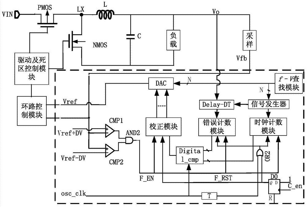
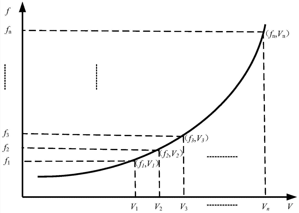
[0039] Take the BUCK power converter as an example, such as figure 1 As shown, VIN is the input voltage of the adaptive voltage regulator; V O is the output voltage of the adaptive voltage regulator; Vfb is the voltage signal after sampling the output voltage, and Vref is the output voltage of the DAC; the signal generator module is a circuit that can generate a corresponding frequency clock signal according to the peripheral control word; Delay The -DT part is the delay line detection module; L is the energy storage inductor; C is the filter capacitor; the frequency voltage (f—V) search module is the working frequency and voltage relationship diagram required by the load in normal operation, specifically as figure 2 shown. C_en is the coarse adjustment enable signal, which is connected to the clock signal terminal of the D flip-flop (D0); osc_clk is the system clock signal provided by the outside, which provides the clock signal to the digital error comparator Digital_cmp, ...


PUM


Abstract

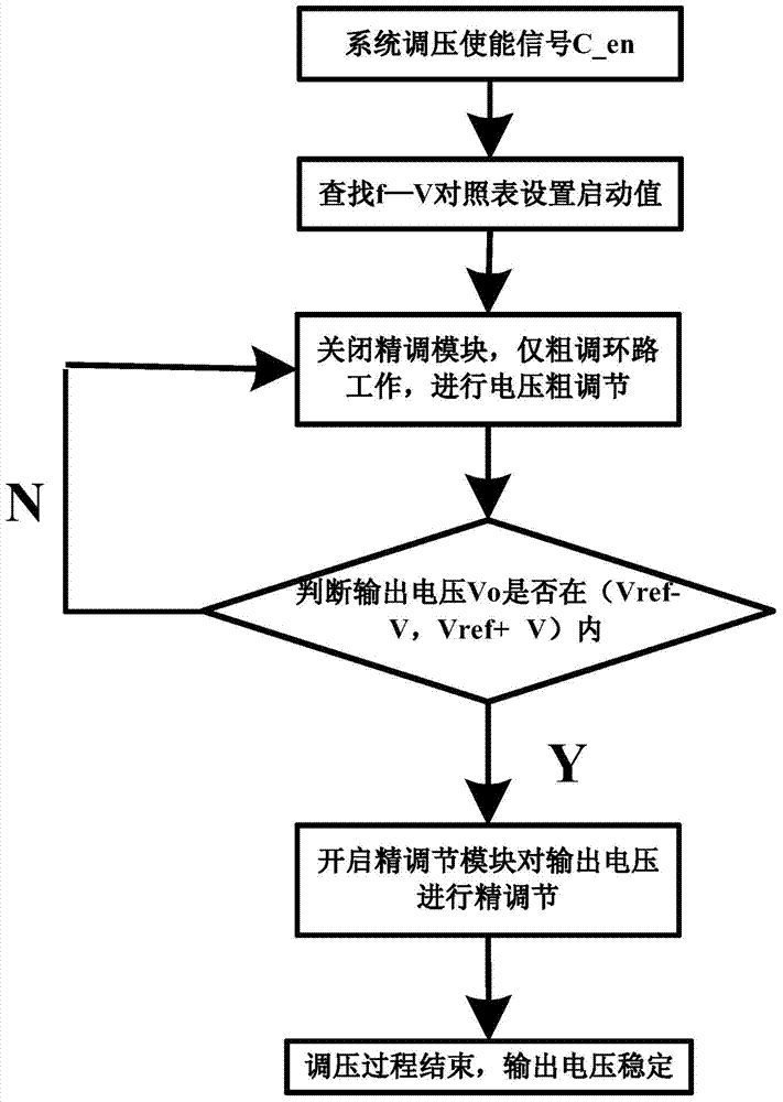
The invention relates to electronic circuit technology, particularly to a dual-ring control self-adapting voltage adjusting method and device. The dual-ring control self-adapting voltage adjusting method provided by the invention comprises the following steps: the target value of output voltage is set and a voltage coarse adjusting loop circuit is started to carry out coarse adjustment to a reference voltage according to loaded working frequency, the coarse adjusting loop circuit is used for quickly adjusting the reference voltage with a larger interval value and sampling the output voltage of a voltage regulator in a real-time manner, whether a voltage sampling value reaches a preset coarse adjusting objective voltage range or not is judged through a comparator, and after the voltage sampling value reaches the objective voltage range, a voltage accurate adjusting loop circuit is started to carry out accurate adjustment to the reference voltage, so as to enable the output voltage of the self-adapting voltage adjusting circuit to be stabilized at an output voltage objective value. The method and the device have the benefits that the voltage adjusting speed is fast, and the output voltage is enabled to be the lowest under the condition of meeting the requirements of load normal work. The method and the device, provided by the invention are applicable to self-adapting voltage adjusters.

Description

technical field [0001] The invention relates to electronic circuit technology, in particular to a dual-loop control self-adaptive voltage regulation method and device. Background technique [0002] In recent years, with the continuous development of semiconductor technology, the feature size of devices has become smaller and smaller, and the scale, operating speed and power consumption of integrated circuits have been greatly improved, enabling us to integrate multiple chips on one chip. Integrated on the same chip (SoC), the performance of the system is improved while reducing the occupied area of ​​the chip and the volume of the electronic system, which greatly promotes the development of portable electronic devices. [0003] The most important criterion for the evaluation of portable consumer electronics products is the size of their power consumption or the length of standby time, but because the development speed of battery technology seriously lags behind the growth ra...

Claims


Application Information

Patent Timeline
IPC IPC(8): G05F1/618
Inventor 罗萍彭宣霖李航标付松林刘磊甄少伟张波
Owner UNIV OF ELECTRONICS SCI & TECH OF CHINA
Learn More