Improved wire cut electrical discharge machine tool

A technology for cutting machine tools and EDM wires, which is applied in electrode manufacturing, electric machining equipment, metal processing machinery parts, etc., and can solve the problems of large voltage loss and low machining efficiency of machine tools.

Inactive Publication Date: 2014-02-12
JIANGSU SANXING MACHINERY MFG
View PDF6 Cites 4 Cited by
  • Summary
  • Abstract
  • Description
  • Claims
  • Application Information

AI Technical Summary

Problems solved by technology

[0002] In the prior art, the wire electric discharge machine tool is composed of the machine tool body and the control cabinet on one side of the machine tool. The high-frequency pulse power generating device is located in the control cabinet on the side of the machine tool, and the positive pole of the high-frequency pulse power generated by it is connected to the machine tool through a wire. The workbench of the main body, the negative electrode of the high-frequency pulse power generated by it is connected to the upper and lower conductive blocks on the side of the upper and lower capstan wheels in the machine tool processing area through wires, and the general distance is 3-4 meters. The disadvantage is that , due to the long distance, the voltage loss is large during the transmission process, and the machining efficiency of the machine tool is low, so it needs to be improved

Method used


Image

  • Improved wire cut electrical discharge machine tool

Examples


Embodiment Construction

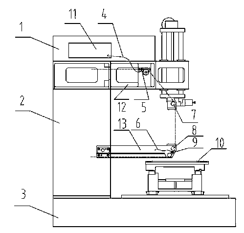
[0018] See attached figure 1 , an improved wire electric discharge machine tool, including a machine tool body and a control cabinet, wherein the machine tool body includes a bed body 3, a wire transport mechanism installed in a cavity of a column 2, a wire rack, a workbench 10, a working fluid system, and a power supply system , machine tool electrical appliances and numerical control system,

[0019] The power system includes a high-frequency pulse power generator 11,

[0020] The wire frame includes a column 2 fixed on the bed and an upper arm 12 and a lower arm 13 connected to the column. The upper arm and the lower arm processing area are respectively equipped with an upper capstan 7, a lower capstan 8 and an upper conductive block 5. , the lower conductive block 9,

[0021] The workbench 10 includes the lower carriage, the upper carriage, the carriage motor, the workbench carriage guide pair, and the transmission assembly. Driven by the carriage motor, the workbench ca...


PUM


Abstract

The invention relates to an improved wire cut electrical discharge machine tool which comprises a machine tool body and a control cabinet. The machine tool body at least comprises a tool body, a wire electrode conveying mechanism, a wire support, a work table, a working solution system, a power supply system, a machine tool electric appliance and a numerical control system. The power supply system comprises a high-frequency pulse power generating device. The wire support comprises a column, an upper arm and a lower arm. An upper main guide wheel and an upper electric conduction block are arranged on one side of a machining area of the upper arm, a lower main guiding wheel and a lower electric conduction block are arranged on one side of a machining area of the lower arm. The high-frequency pulse power generating device is arranged in a power supply cabinet, the power supply cabinet is arranged on one side of the column, a positive pole of generated high-frequency pulse power is connected with the work table of the machine tool body through a lead, and a negative pole of the generated high-frequency pulse power is connected with the upper electric conduction block on one side of the upper main guide wheel and the lower electric conduction block on one side of the lower main guide wheel of a machining area of the machine tool through an upper lead and a lower lead respectively. The distance between the high-frequency pulse power and the upper electric conduction block and the distance between the high-frequency pulse power and the lower electric conduction block are greatly shortened and can be approximately shortened by half, voltage loss in a conveying process is small, and machining efficiency of the machine tool is remarkably improved.

Description

technical field [0001] The invention relates to an improved electric discharge wire cutting machine tool, which belongs to the technical field of electric discharge wire cutting machine tools. Background technique [0002] In the prior art, the wire electric discharge machine tool is composed of the machine tool body and the control cabinet on one side of the machine tool. The high-frequency pulse power generating device is located in the control cabinet on the side of the machine tool, and the positive pole of the high-frequency pulse power generated by it is connected to the machine tool through a wire. The workbench of the main body, the negative electrode of the high-frequency pulse power generated by it is connected to the upper and lower conductive blocks on the side of the upper and lower capstan wheels in the machine tool processing area through wires, and the general distance is 3-4 meters. The disadvantage is that , due to the long distance, the voltage loss is lar...

Claims


Application Information

Patent Timeline
IPC IPC(8): B23H7/02B23H7/10B23Q1/25
Inventor 王炎秋
Owner JIANGSU SANXING MACHINERY MFG
Why Eureka
Try Eureka