
Precise locating method for automatic assembly hole making

A technology of precise positioning and hole position, applied in the direction of manufacturing tools, metal processing machinery parts, measuring/indicating equipment, etc., can solve the problems of reducing the accuracy of hole making, prone to failure, and increasing the time of hole making process, so as to save complex Calculation, the effect of improving machining accuracy

Active Publication Date: 2014-01-22
航天海鹰(镇江)特种材料有限公司
View PDF7 Cites 18 Cited by
  • Summary
  • Abstract
  • Description
  • Claims
  • Application Information

AI Technical Summary

Problems solved by technology

The disadvantage is that it is necessary to accurately pre-position the reference hole in the state of the product part, and then use it as a reference to form a certain processing range, and since all hole-making programs are based on theoretical digital models for off-line programming, attitude adjustment is a key step in each hole-making process. a process that must be done
The accuracy of attitude adjustment reduces the accuracy of hole making and increases the process time of hole making
The control radius of the prefabricated reference hole of the part is limited, and a large number of accurate reference holes need to be prefabricated in advance. The error accumulation of the prefabricated reference hole of the part itself, and the error during assembly will reduce the hole position accuracy, aperture, and countersinking of the overall component. Dimple precision, resulting in many processes for automatic hole making of large components, complex procedures, increased computational difficulty, prone to failures, and it is difficult to guarantee high efficiency, large size, high precision automatic hole making processing

Method used


Image

  • Precise locating method for automatic assembly hole making
  • Precise locating method for automatic assembly hole making

Examples


Embodiment Construction

[0011] Below in conjunction with accompanying drawing and specific embodiment, further illustrate the present invention, should be understood that these embodiments are only for illustrating the present invention and are not intended to limit the scope of the present invention, after having read the present invention, those skilled in the art will understand various aspects of the present invention Modifications in equivalent forms all fall within the scope defined by the appended claims of this application.

[0012] Taking a large aircraft aileron as an example, the specific implementation process of the method of the present invention is described.

[0013] After assembling and positioning the middle rib of the aileron, the pre-connected part of the standard parts forms a stable component to reach the hole-making state, that is, it has a certain rigidity and can be clamped on the assembly frame to meet the non-deformed state during processing of the five-axis machining center...


PUM


Abstract

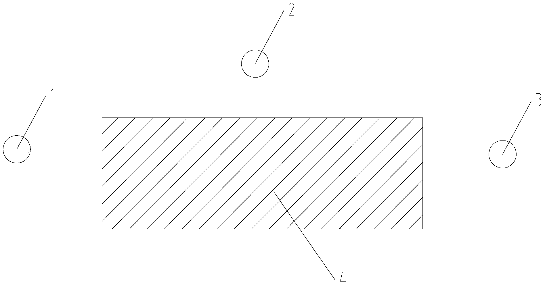
The invention discloses a precise locating method for automatic assembly hole making. A hole making system is composed of a five-axis machining machine tool and a laser tracker. A product is mounted on an assembly fixture and made to be in a stable hole making state, the product and the assembly fixture are together moved to the five-axis machining center and fixed, the laser tracker is used for building a coordinate system through datum points of the assembly fixture, the appearance contour of the product is scanned, a solid numerical model is generated from a point cloud obtained by scanning in the reverse direction, measuring software is used for automatically generating a hole site closest to the 3D space of appearance contour mathematical points of the product in space on the surface of the solid numerical model, and the hole site is used as the basis of five-axis machining hole making. The precise locating method has the advantages that machining precision is improved, complex operation and repeated calibration in the hole making process are omitted, precision of the hole making locating degree, the perpendicularity and the reaming cavity depth is better than the requirement of automatic hole making specifications, an expensive end effector is not needed, manufacturing cost is lowered, and production efficiency is maximized.

Description

technical field [0001] The invention relates to a positioning method for assembling holes, in particular to a precise positioning method for reducing the deviation between actual values ​​and theoretical values ​​when assembling automatic hole making. Background technique [0002] At present, the automatic hole-making system for aircraft assembly uses a robotic arm or a five-axis machining tool as the main driving positioning system, combined with an end effector to make holes. The mechanical arm and the five-axis hole-making equipment move to the theoretical digital model position through offline programming according to the theoretical digital model of the product hole position. However, there is an error between the actual product and the theoretical digital model. If it is directly processed according to the theoretical digital model, it will cause The normal direction of the hole is out of tolerance and the precision of the spot facing is out of tolerance. The current ...

Claims


Application Information

Patent Timeline
IPC IPC(8): B23Q17/20B23Q17/24
CPCB23Q17/20B23Q17/2471
Inventor 魏洪峰郭渊陆明富高乾坤刘园园朱志为仲镇朱云安贾傲罗德意包立敏
Owner 航天海鹰(镇江)特种材料有限公司
Learn More