
A bulk silicon mosfet structure

A variant, a technology of silicon metal, applied in the field of bulk silicon MOSFET structure, can solve the problems of high manufacturing cost, achieve low cost, suppress single-event radiation effect, and improve the effect of single-event radiation effect

Active Publication Date: 2016-05-04
HARBIN ENG UNIV
View PDF5 Cites 0 Cited by
  • Summary
  • Abstract
  • Description
  • Claims
  • Application Information

AI Technical Summary

Problems solved by technology

[0005] The embodiment of the present invention proposes a bulk silicon MOSFET structure, which can be used in MOS devices to solve the problem of high manufacturing cost in the existing SOI technology

Method used


Image

  • A bulk silicon mosfet structure
  • A bulk silicon mosfet structure

Examples


Embodiment Construction

[0016] The present invention is described in detail below in conjunction with accompanying drawing example:

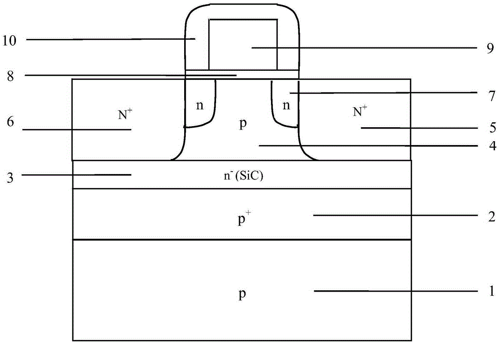
[0017] figure 1 Shown is the radiation-hardened structure of the bulk silicon MOSFET proposed in this paper. exist figure 1 Among them, 1 is p-type substrate; 2 is p + Low carrier lifetime silicon layer; 3 is n - SiC layer; 4 is p-type body region; 5 is N + Drain terminal; 6 is N + Source terminal; 7 is n-type LDD structure; 8 is gate oxide layer; 9 is polysilicon gate; 10 is Si 3 N 4 side wall.

[0018] Starting from the bottom of the device, above the p-type substrate 1 is a p + Low carrier lifetime silicon layer 2; p + An n - Layer 3 (also known as n - SiC layer or SiC layer), this layer is made of silicon carbide (SiC) material; above the SiC layer 3, the left and right sides are respectively the source region 6 of the device (also called N + source) and drain region 5 (also referred to as N + drain terminal), the middle is a p-type body region 4 , and...


PUM


Abstract

The invention discloses a bulk-silicon MOSFET (METAL-OXIDE-SEMICONDUCTOR FIELD-EFFECT TRANSISTOR) structure. The bulk-silicon MOSFET structure comprises a p+ layer (2) and an n- layer (3), wherein the p+ layer (2) and the n- layer (3) are directly contacted; the n- layer is made of wide-bandgap 6H-SiC material. The bulk-silicon MOSFET structure disclosed by the invention has the advantage that the radiation resistance of the bulk-silicon structure is improved. Compared with the SOI (Silicon On Insulator) technology, the bulk-silicon MOSFET structure disclosed by the invention has the beneficial effects that the self-heating effect is improved, the total dosage effect is eliminated, and the cost is reduced.

Description

technical field [0001] The invention relates to the field of semiconductors, in particular to a bulk silicon MOSFET structure. Background technique [0002] The concept of metal oxide semiconductor (METAL-OXIDE-SEMICONDUCTOR, MOS) transistor was first proposed by Lilienfield in 1930. However, it was not until 1960 that KAHNG and others successfully used silicon semiconductor materials to make the first MOS transistor. Then in 1964, SNOW and others proposed a technology to grow highly reliable oxides by conventional methods, which made MOS technology truly practical and developed rapidly in the following decades. Now, Metal Oxide Semiconductor Field Effect Transistor (MOSFET) has become the most important electronic device in the information industry. The semiconductor integrated circuit industry with MOS technology as the core has also achieved amazing development in the past few decades. [0003] The theory of MOS device scaling down is constantly shrinking in size, and ...

Claims


Application Information

Patent Timeline
Patent Type & Authority Patents(China)
IPC IPC(8): H01L29/78H01L29/06
CPCH01L29/0642H01L29/7836
Inventor 王颖贺晓雯曹菲邵雷
Owner HARBIN ENG UNIV
Learn More