
Device and method for automatically calibrating performance parameters of CCD (Charge Coupled Device)

An automatic calibration and parameter technology, which is applied in the direction of testing optical performance, can solve the problems of difficulty in ensuring repeatability and test accuracy, inability to realize automatic testing, and lack of unified control, so as to avoid unstable factors, avoid errors, and improve confidence degree of effect

Inactive Publication Date: 2014-01-08
XI'AN INST OF OPTICS & FINE MECHANICS - CHINESE ACAD OF SCI
View PDF5 Cites 10 Cited by
  • Summary
  • Abstract
  • Description
  • Claims
  • Application Information

AI Technical Summary

Problems solved by technology

The linear adjustment of the output power of the laser, the continuous exposure of the CCD, and the continuous detection of the laser power by the power detector are independent of each other. Without unified control, it is impossible to realize automatic testing in the true sense, and the CCD is in the process of frame transfer. There will be tailing
The entire testing process requires the participation of testers, and the influence of personnel operations cannot be avoided. It is difficult to guarantee repeatability and test accuracy.

Method used


Image

  • Device and method for automatically calibrating performance parameters of CCD (Charge Coupled Device)
  • Device and method for automatically calibrating performance parameters of CCD (Charge Coupled Device)
  • Device and method for automatically calibrating performance parameters of CCD (Charge Coupled Device)

Examples


Embodiment Construction

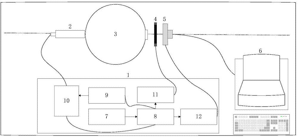
[0038] Such as figure 1 As shown, the present invention is composed of a control module 1 , a pulsed laser 2 , an integrating sphere 3 , a mechanical shutter 4 , a tested CCD detector 5 and a main control computer 6 . Among them, the control module 1 is composed of a clock pulse generation circuit 7 , an automatic pulse width adjustment circuit 8 , an output pulse driving capability amplification circuit 9 , a power module 10 , a shutter control circuit 11 and a CCD trigger signal output circuit 12 . The specific working process is as follows:

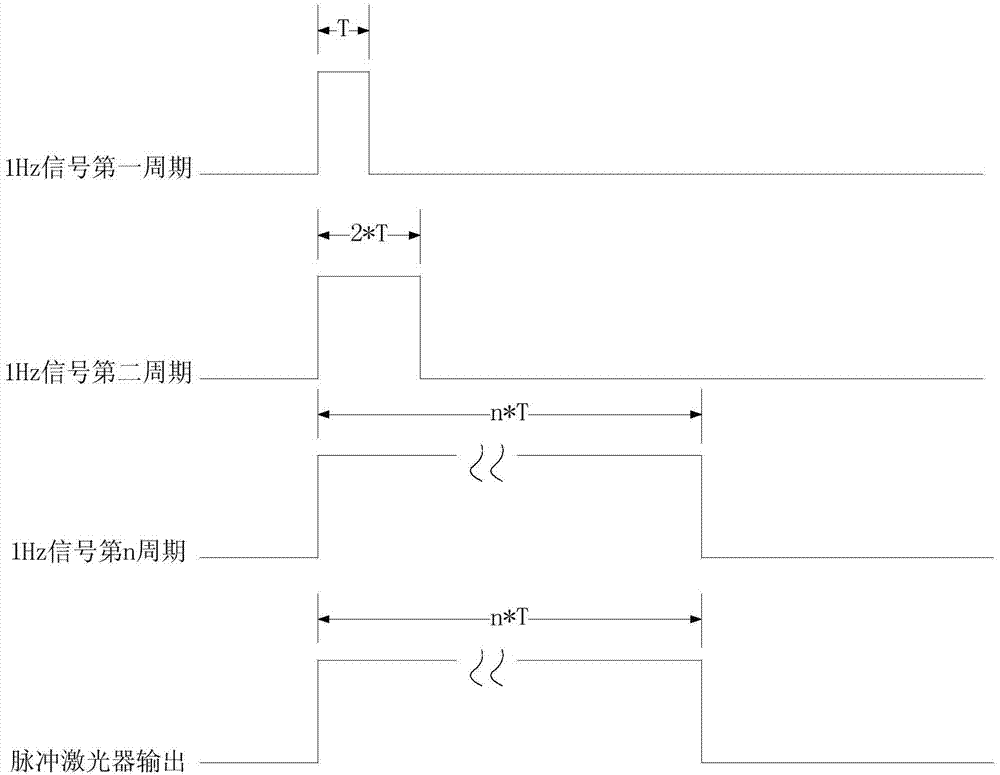
[0039](1) The pulse laser output pulse excitation period is T, and a clock signal with a frequency of 1 Hz is generated by a clock pulse generation circuit. Set the initial pulse width to the pulse laser output pulse excitation period, and its frequency stability is -9 , frequency accuracy -7 .

[0040] (2) 2s before the automatic test starts, the CCD trigger signal output circuit triggers the CCD exposure, and the image data at this...


PUM


Abstract

The invention relates to a device and a method for automatically calibrating performance parameters of a CCD (Charge Coupled Device). The device for automatically calibrating the performance parameters of the CCD comprises a control module, a pulse laser, an integrating sphere, a mechanical shutter, a detected CCD detector and a main control computer which are sequentially connected, wherein the control module comprises a clock pulse generating circuit, a pulse width automatic regulating circuit, an output pulse drive capability amplifying circuit, a power supply module, a shutter control circuit and a CCD trigger signal output circuit, the pulse width automatic regulating circuit, the output pulse drive capability amplifying circuit and the power supply module are sequentially connected, the shutter control circuit is respectively connected with the pulse width automatic regulating circuit and the mechanical shutter, and the CCD trigger signal output circuit is respectively connected with the pulse width automatic regulating circuit and the detected CCD detector; the power supply module comprises a laser drive power supply and a power supply temperature acquisition system, and the power supply module is also connected with the pulse laser and the pulse width automatic regulating circuit. The device and the method for automatically calibrating the performance parameters of the CCD, provided by the invention, have the advantages of high stability, high accuracy, high confidence coefficient and simpleness in operation.

Description

technical field [0001] The invention belongs to the field of photoelectric testing, and relates to a device and method capable of precisely controlling the linear output of pulsed laser power and synchronous acquisition by CCD, so as to automatically calibrate parameters such as the dynamic range, nonlinearity, and signal-to-noise ratio of an area array CCD, and in particular to a device and method A device and method for automatic calibration of CCD performance parameters. Background technique [0002] In the high-power laser device of the National Science and Technology Project, the CCD is usually used to collect near-field images, and then the laser near-field indicators are obtained through calculation. In order to reduce the impact of the performance parameters of the CCD itself on the near-field test, it is necessary to strictly screen and calibrate the selected CCD. [0003] The dynamic range, nonlinearity and signal-to-noise ratio of CCD are important parameters to ...

Claims


Application Information

Patent Timeline
Patent Type & Authority Applications(China)
IPC IPC(8): G01M11/02
Inventor 龙江波赵建科段亚轩李坤田留德薛勋
Owner XI'AN INST OF OPTICS & FINE MECHANICS - CHINESE ACAD OF SCI
Learn More