
A method for circular seam laser-gma composite welding

A -GMA, composite welding technology, applied in the direction of laser welding equipment, welding equipment, metal processing equipment, etc., can solve the problems of discontinuous formation of the back of the weld, incomplete penetration, and the next trip of liquid metal, so as to shorten the working cycle, The effect of sufficient flow and continuous forming

Active Publication Date: 2016-01-20
HARBIN INST OF TECH
View PDF5 Cites 0 Cited by
  • Summary
  • Abstract
  • Description
  • Claims
  • Application Information

AI Technical Summary

Problems solved by technology

[0007] The purpose of the present invention is to provide a circular seam laser-GMA hybrid welding in order to solve the problems of discontinuous formation of the back of the weld, liquid metal on the surface and incomplete penetration in the existing circular seam laser-GMA arc hybrid welding Methods

Method used


Image

  • A method for circular seam laser-gma composite welding
  • A method for circular seam laser-gma composite welding
  • A method for circular seam laser-gma composite welding

Examples


specific Embodiment approach 1

[0021] Specific implementation mode 1: The method for circular seam laser-GMA composite welding in this implementation mode is realized according to the following steps:

[0022] 1. Groove processing: machine the butt joint of the parts to be welded to produce a Y-shaped groove with a groove angle of 30-70° and a blunt edge size of 3-8mm, and then use mechanical grinding to remove the groove surface Oxide layer, and then use acetone to clean the oil on the groove surface;

[0023] 2. Spot solidification: Use a single laser to spot solidify the blunt edge of the weld groove at two positions 180° apart from each other on the girth weld. The spot solid laser power is 500-2000W, and the light emission time is 1-2s;

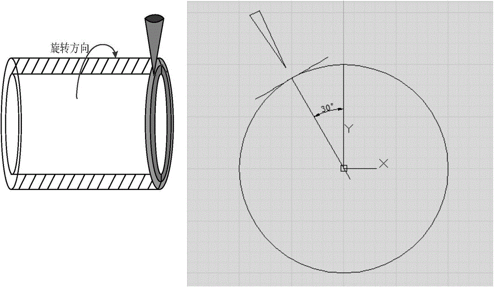
[0024] 3. Welding: Set the process parameters, the laser beam and the GMA welding torch form an angle of 45°, the incident point of the laser beam is positioned at the 11 o'clock position of the circular seam, and the distance between the laser beam and the arc heat s...

specific Embodiment approach 2

[0029] Embodiment 2: The difference between this embodiment and Embodiment 1 is that in Step 1, the bevel angle is 45°, and the size of the blunt edge is 4mm. Other steps and parameters are the same as those in Embodiment 1.

specific Embodiment approach 3

[0030] Embodiment 3: The difference between this embodiment and Embodiment 1 or 2 is that the power of the spot-fixed laser in step 2 is 1000W, and the light emitting time is 1.5s. Other steps and parameters are the same as those in Embodiment 1 or Embodiment 2.


PUM

PropertyMeasurementUnit
angleaaaaaaaaaa
sizeaaaaaaaaaa

Abstract

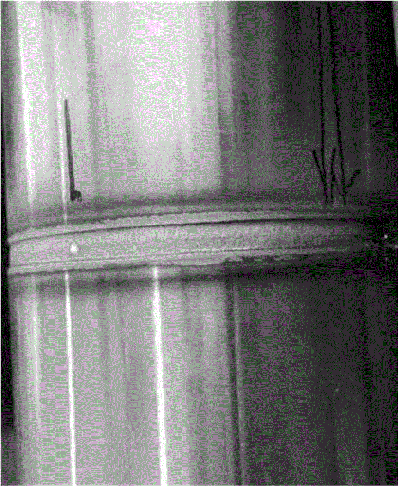
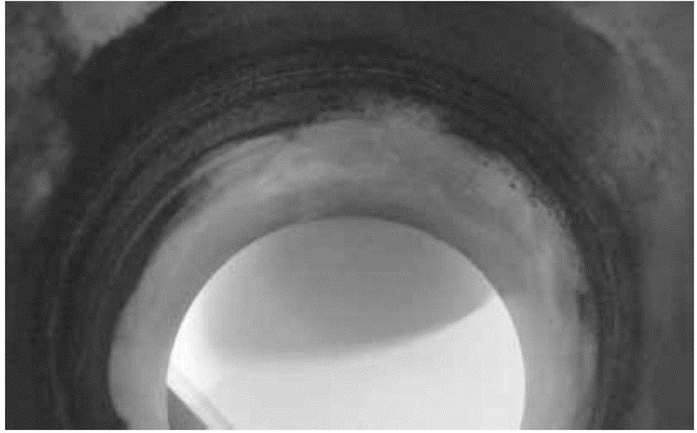
A girth laser-GMA hybrid welding method relates to the field of materials processing engineering, and mainly solves the problems of the conventional girth laser-GMA arc hybrid welding that the welding line reverse side forming is in-continuous, liquid metal and incomplete-penetrating are existent on the surface. The method comprises the following steps: firstly, edge preparation; secondly, dot solidification; thirdly, welding, that is, accomplishing girth laser-GMA hybrid welding. According to the method provided by the invention, laser beam enters and arcs from the angle of 11 o 'clock, the method is high the automatic degree, high in stability, deep in penetration, low in thermal input, and better in interval adaptive capacity, preheating and reassembly link are eliminated, welding production efficiency is improved. According to the girth laser-GMA hybrid welding method provided by the invention, welding line reverse side forming is continuous, liquid metal and incomplete-penetrating are not existent on the surface.

Description

technical field [0001] The invention relates to a laser-GMA composite welding method for the girth weld of a closed tank body, belonging to the field of material processing engineering. Background technique [0002] The girth weld joint is a very common joint form, which is widely used in the welding of oil pipelines, pressure vessel storage tanks, aircraft, missiles, ships and other gas storage and liquid storage tanks. The main welding processes of pipe girth welds in my country are: combined process of cellulose electrode and self-shielded flux cored wire semi-automatic welding (SMAW+FCAW, usually called semi-automatic welding), argon-rich mixed gas shielded automatic welding process (GMAW, usually called Automatic welding) and the combined process of cellulose electrodes and low hydrogen electrodes (SMAW, often called manual welding). Among them, the West-East Gas Pipeline Project mainly uses self-shielding flux-cored wire semi-automatic welding and all-position automati...

Claims


Application Information

Patent Timeline
Patent Type & Authority Patents(China)
IPC IPC(8): B23K26/348
Inventor 雷正龙陈彦宾刘申胡佩佩杨斯达董智军
Owner HARBIN INST OF TECH
Learn More