
Hydraulic cylinder with built-in stroke detecting device

A stroke detection and hydraulic cylinder technology, which is applied in the field of hydraulic cylinders, can solve the problems of stroke detection length limitation, labor and time-consuming, large shape, etc., and achieve the effects of eliminating cumulative errors, reducing use costs, and reducing volume

Inactive Publication Date: 2013-10-30
JIANGSU WUJIN HYDRAULIC HOIST +1
View PDF6 Cites 5 Cited by
  • Summary
  • Abstract
  • Description
  • Claims
  • Application Information

AI Technical Summary

Problems solved by technology

The above two built-in stroke detection devices are not only large in shape, but must be used in ample space, and the installation process is more troublesome, especially when the hydraulic cylinder needs to be opened for maintenance, the whole process is laborious and time-consuming
[0003] Although the existing hydraulic cylinder with a built-in stroke detection device overcomes the corrosion resistance and wear resistance of the original chrome-plated piston rod surface is not good enough, and the built-in stroke detection of the original hydraulic cylinder using a chrome-plated piston rod The stroke detection length of the device is limited, the built-in stroke detection device has a large shape, and the installation and maintenance are troublesome. However, the operation of the piston rod before detection will generate cumulative errors, which will affect the detection accuracy.
In addition, the existing stroke detection sensor is also relatively large in size, with a large number of cable cores, complex structure and high cost.

Method used


Image

  • Hydraulic cylinder with built-in stroke detecting device
  • Hydraulic cylinder with built-in stroke detecting device
  • Hydraulic cylinder with built-in stroke detecting device

Examples


Embodiment Construction

[0016] The present invention is described in further detail now in conjunction with accompanying drawing. These drawings are all simplified schematic diagrams, which only illustrate the basic structure of the present invention in a schematic manner, so they only show the configurations related to the present invention.

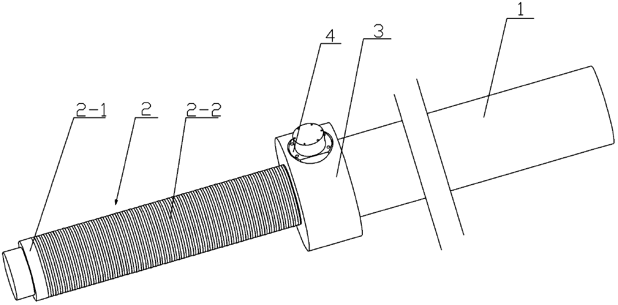
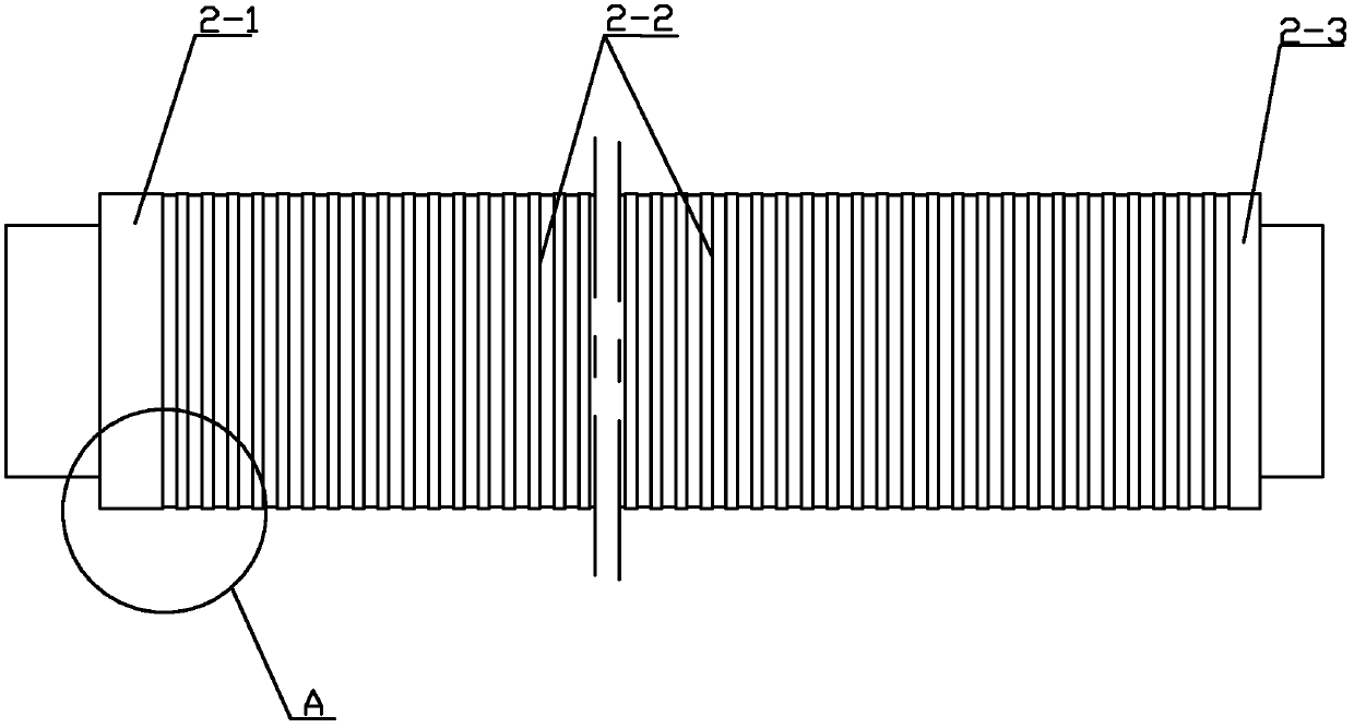
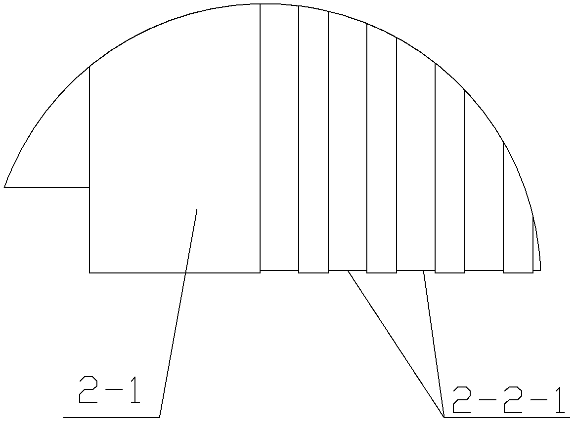
[0017] Such as Figure 1 ~ Figure 4 Shown is the optimal embodiment of the hydraulic cylinder with a built-in stroke detection device in the present invention, a hydraulic cylinder with a built-in stroke detection device, which has a cylinder body 1, a ceramic piston rod 2, a lower end cover 3 and a sensor 4, and a ceramic piston rod 2 There is a stroke detection section on the top, and the stroke detection section is divided into a start section 2-1, a stroke section 2-2 and an end section 2-3, and the stroke section 2-2 is equidistantly provided with grooves 2- 2-1, the width of the starting section 2-1 and the ending section 2-3 is not less than twice the ...


PUM


Abstract

The invention relates to a hydraulic cylinder, in particular to a hydraulic cylinder with a built-in stroke detecting device. The hydraulic cylinder comprises a cylinder body, a ceramic piston rod, a lower end cover and a sensor. A stroke detecting section is arranged on the ceramic piston rod and is divided into a start section, a stroke section and a finish section, grooves with equal widths are equidistantly formed in the stroke section, the width of the start section is not smaller than two times the width of each groove, the sensor is close to the surface of the stroke detecting section or is in contact with the surface of the stroke detecting section, and the detection direction of the sensor directly faces the center of the ceramic piston rod and is parallel to the axis of the ceramic piston rod. The hydraulic cylinder has the advantages that accumulated errors due to interference during running can be eliminated; the quantity of cable cores of the sensor is reduced, the sensor is only provided with a positive power core, a negative power core and a signal core, the cable usage cost is reduced as compared with an existing sensor with a six-core cable, the size of the sensor is reduced and is smaller than one-third of that of a conventional sensor of a ceramic piston rod, and output signals are analog signals and accordingly are good in universality.

Description

technical field [0001] The invention relates to a hydraulic cylinder, in particular to a hydraulic cylinder with a built-in stroke detection device. Background technique [0002] The working environment of the hydraulic hoist is complex and changeable, so the anti-corrosion and wear-resistant performance of the piston rod of the hydraulic cylinder is very high, so the necessary anti-corrosion and wear-resistant treatment must be carried out on the surface to ensure the performance. The traditional process is to electroplate chromium on the surface of the piston rod, and the hexavalent chromium ion in the electroplating chromium has been proved to be a carcinogen. And it has been proved by practice that the electroplated piston rod will inevitably be rusted after being put into operation for many years. Therefore, electrochrome plating is not a method that can fundamentally solve the corrosion resistance of the piston rod. There are two types of built-in stroke detection dev...

Claims


Application Information

Patent Timeline
Patent Type & Authority Applications(China)
IPC IPC(8): F15B15/14F15B15/20F15B15/28
Inventor 吴国栋朱琴玉彭哲凯王双云
Owner JIANGSU WUJIN HYDRAULIC HOIST
Learn More