
Pressure-controlled friction stir welding main shaft head device

A friction stir welding and pressure control technology, applied in welding equipment, manufacturing tools, non-electric welding equipment, etc., can solve the problems of complex structure and control mechanism of FSW equipment, and achieve easy control, simple hydraulic system, simple and compact structure Effect

Inactive Publication Date: 2013-10-16
TIANJIN UNIV
View PDF5 Cites 21 Cited by
  • Summary
  • Abstract
  • Description
  • Claims
  • Application Information

AI Technical Summary

Problems solved by technology

[0005] At present, the pressure control friction stir welding equipment disclosed in the foreign market adopts the structural method of separating the load applying device from the spindle head, and its FSW equipment structure and control mechanism are relatively complicated; while the domestic friction stir welding equipment manufacturer: Beijing Saifusi The friction stir welding equipment released on the market by Special Technology Co., Ltd. (authorized by TWI in 2002) and Shanghai Aerospace Equipment Manufacturing General Factory (authorized by TWI in 2010) are both displacement control mode to apply axial upsetting pressure, and the welding process is established On the basis of friction stir welding equipment in displacement control mode, this leads to obvious limitations in domestic FSW welding equipment automation, process and welding processing efficiency, and weld quality control.

Method used


Image

  • Pressure-controlled friction stir welding main shaft head device
  • Pressure-controlled friction stir welding main shaft head device

Examples


Embodiment

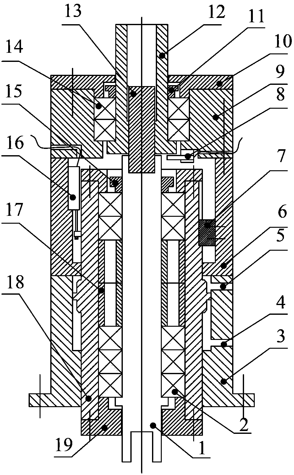
[0042] To manufacture a certain friction stir welding equipment that meets the welding pressure controllable welding, the welding speed range is 100-3000rpm, the welding pressure range is 5-60kN, and a special spindle head is now designed for it. The spindle head can be used as figure 1 The structure shown, its design steps are as follows:

[0043] Bearings are selected according to the spindle speed and axial load requirements: while the spindle rotates at high speed, its axial load capacity must be guaranteed, and angular contact spindle bearings are usually selected; the contact angle of this type of bearing is generally 15° or 25°; In some cases, in order to improve the axial bearing capacity of the main shaft, multiple bearings can be assembled in series; it is recommended that three angular contact bearings with a contact angle of 25° be selected for the bearing group at the front end of the main shaft and arranged in series with TTL.

[0044] Design the size of the sha...


PUM


Abstract

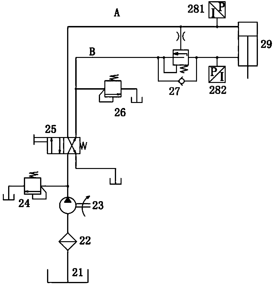
The invention discloses a pressure-controlled friction stir welding main shaft head device which mainly comprises a hydraulic system, a main shaft oil cylinder outer casing and a main shaft piston mechanism, wherein the main shaft oil cylinder outer casing is formed by a front casing and a rear casing which are coaxially connected; the main shaft piston mechanism comprises a main shaft oil cylinder inner casing and a rotating shaft arranged in the main shaft oil cylinder inner casing; the rear end of the rotating shaft is connected with a sliding coupler through a spline shaft; a displacement sensor is arranged between the main shaft oil cylinder outer casing and the main shaft oil cylinder inner casing; a limiting block is arranged between the main shaft oil cylinder outer casing and the main shaft oil cylinder inner casing; a revolution speed transducer is arranged on the sliding coupler; and the length of the spline shaft is larger than the sum of the lengths of the distance between two axial travel spacing steps and a spline connection section. Compared with a structure of a main shaft used in a conventionally disclosed friction stir welding device, the main shaft head device has the characteristics that the dimension is small, the structure is simple, the integration level is high, a rotation driving manner is flexible, the pressure control principle is simple and accurate, and the like.

Description

technical field [0001] The invention belongs to the field of welding equipment manufacturing engineering for metal material processing, and specifically relates to a pressure-controlled friction stir spot welding and friction stir seam welding spindle head device for welding nonferrous metals such as aluminum and magnesium and their alloys. Background technique [0002] Friction Stir Welding (Friction Stir Welding-FSW) is a solid-phase friction welding technology invented by The Welding Institute-TWI in 1991. It is mainly used for non-ferrous metals such as aluminum and magnesium alloys, copper and titanium alloys. Alloy connections. FSW has many advantages that cannot be compared with traditional fusion welding methods: for example, the welding process does not require groove preparation, filler metal and shielding gas; the quality and mechanical properties of welded joints have been significantly improved; welding deformation is small, low defect levels and high production...

Claims


Application Information

Patent Timeline
Patent Type & Authority Applications(China)
IPC IPC(8): B23K20/12
Inventor 杨新岐崔雷侯晓鹏
Owner TIANJIN UNIV
Learn More