
Method for acknowledging rebound value of rebound instrument

A rebound rebound meter and rebound value technology, which is applied in the direction of testing the hardness of materials, etc., can solve the problems that the energy of the object to be tested cannot be directly and accurately reflected, and the accuracy is not high.

Inactive Publication Date: 2013-10-09
曾汉
View PDF6 Cites 8 Cited by
  • Summary
  • Abstract
  • Description
  • Claims
  • Application Information

AI Technical Summary

Problems solved by technology

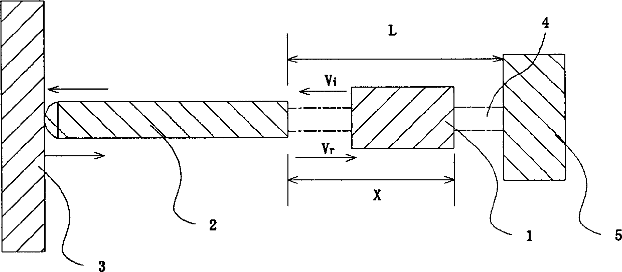
In the actual detection, the above-mentioned rebound value confirmation method has the following disadvantages: if the mass of the bullet hammer is M, the mass of the bullet hammer is m, and the impact velocity of the bullet hammer is V when it is moving in a free state. i , the rebound velocity V in the free state after the impact r , the compressive stiffness of the spring k, the working length of the spring L, and the springback length X of the hammer after the rebound test of the rebound tester is completed, such as figure 1 As shown; since the impact of the impact hammer 1 on the impact rod 2 is accompanied by vibration, sound energy, heat energy and deformation energy loss, the kinetic energy of the impact hammer 1 is equal to the penetration of the impact rod 2 into the object 3 (such as The resistance work W of concrete) and the energy W consumed by the impact of the impact hammer 1 on the impact bar to generate vibration 1 The energy consumed by friction with each component of the rebound hammer W 2 Sum
Therefore, in the actual engineering inspection, the distance L between the bouncing hammer 1 and the bouncing rod 2 before the collision is a fixed value set in advance, and the rebound distance X of the bouncing hammer 1 drives a pointer block along the rebounding direction through the bouncing hammer 1. The scale movement on the instrument is displayed to the user, so the rebound value measured by reading the position of the pointer block cannot directly and accurately reflect the energy conversion of the object under test, and its accuracy is not high

Method used


Image

  • Method for acknowledging rebound value of rebound instrument
  • Method for acknowledging rebound value of rebound instrument
  • Method for acknowledging rebound value of rebound instrument

Examples


Embodiment Construction

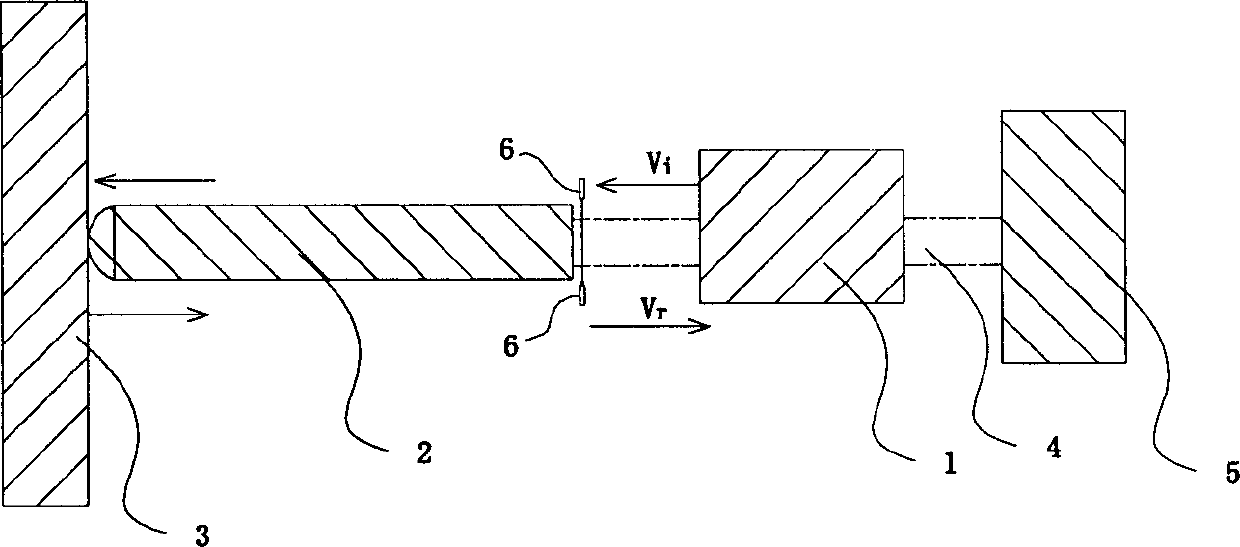
[0029] Attached below figure 2 The specific implementation and theoretical basis of the method for confirming the rebound value of the rebound hammer involved in the present invention will be further described in detail.

[0030] A method for confirming the rebound value of a rebound hammer, which includes the following steps:

[0031] 1) Use a spring to drive the bouncing hammer 1 to strike the bouncing rod 2, and the bouncing rod 2 will collide with the object under test 3 after being hit;

[0032] 2) Use the sensor 6 to measure and read the impact velocity Vi of the impact hammer 1 when it hits the impact bar 2;

[0033] 3) Use the sensor 6 to measure and read the rebound velocity Vr of the bouncing hammer after the bouncing hammer 1 hits the bouncing rod 2;

[0034] 4) The value obtained by dividing the rebound velocity Vr by the impact velocity Vi is used as the rebound value of the rebound hammer.

[0035] In step 1), driving the spring hammer 1 and impacting the obj...


PUM


Abstract

The invention provides a method for acknowledging a rebound value of a rebound instrument. The method comprises the following steps of: (1) driving a springing hammer through a spring to strike a springing rod, and striking an object to be detected after the springing rod is struck; (2) reading an impact speed Vi, at which the springing hammer strikes the springing rod, through a sensor; (3) reading a rebound speed Vr of the springing hammer after the springing hammer strikes the springing rod through the sensor; (4) dividing the rebound speed Vr by the impact speed Vi to obtain a value which serves as the rebound value of the rebound instrument. By the adoption of the method, the detection accuracy of the rebound instrument can be improved.

Description

technical field [0001] The invention relates to a method for detecting the strength of materials and components with a rebound hammer in the field of construction engineering, such as detecting the compressive strength of concrete and mortar; specifically, it refers to a method for confirming the rebound value of a rebound hammer. Background technique [0002] The rebound hammer was invented by Swiss engineer E.Schmidt in 1948. Its working principle is similar to that of the Shore hardness tester, and it is a dynamic hardness measurement method. The Shore hardness test method was proposed by A.F.SHore of the United States in 1907. It is widely used in metallurgy and machinery industries, and is especially suitable for on-site hardness measurement of large metal test pieces such as rolls, machine tool beds, and large gears. The basic principle is: an impact body with a certain shape and quality and a diamond tip falls freely from a fixed height (H) to the surface of the sampl...

Claims


Application Information

Patent Timeline
Patent Type & Authority Applications(China)
IPC IPC(8): G01N3/52
Inventor 曾利民辛新曾汉
Owner 曾汉
Learn More