Soil dynamic test device

A test device and soil technology, applied in the direction of applying repeated force/pulsation force to test the strength of materials, etc., can solve the problems of heavy workload, inaccurate test results, high cost, etc., and achieve the effect of convenient operation

Pending Publication Date: 2018-11-06
OCEAN UNIV OF CHINA
View PDF0 Cites 2 Cited by
  • Summary
  • Abstract
  • Description
  • Claims
  • Application Information

AI Technical Summary

Problems solved by technology

[0004] The present invention proposes a soil dynamic testing device, which solves the problem of inaccurate test results, heavy workload and high cost caused by the inability of the dynamic triaxial instrument and wave tank in the prior art to effectively simulate the liquefaction of seabed soil under the action of waves. question

Method used


Image

  • Soil dynamic test device
  • Soil dynamic test device
  • Soil dynamic test device

Examples


Embodiment 1

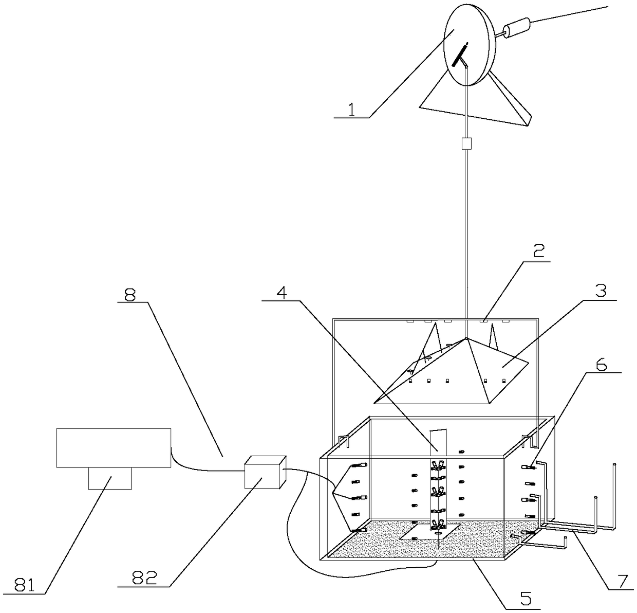
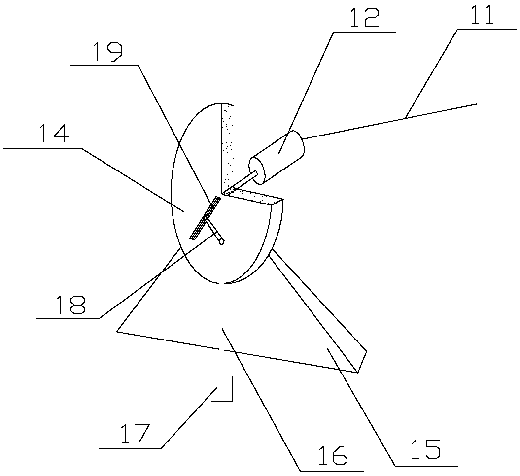
[0036] See attached figure 1 , attached figure 2 , attached image 3 , attached Figure 4 , attached Figure 5 , attached Figure 6 , attached Figure 7 , attached Figure 8 , attached Figure 9 And attached Figure 10 , the present invention comprises a test box 5, the bottom of the test box 5 is paved with soil, the inside of the test box 5 is filled with seawater, and the test box 5 is provided with a pressure measuring mechanism 6 for testing the inner soil pressure and pore pressure, The top of the test box 5 is connected with a loading plate mechanism 3; the loading plate mechanism 3 is connected with a cyclic power mechanism 1 that drives it to reciprocate linearly along the vertical direction, and the loading plate mechanism 3 is also connected with a displacement device for detecting its motion displacement Measuring mechanism 2, pressure measuring mechanism 6 is connected with computer control mechanism 8, and displacement measuring mechanism 2 is also conne...

Embodiment 2

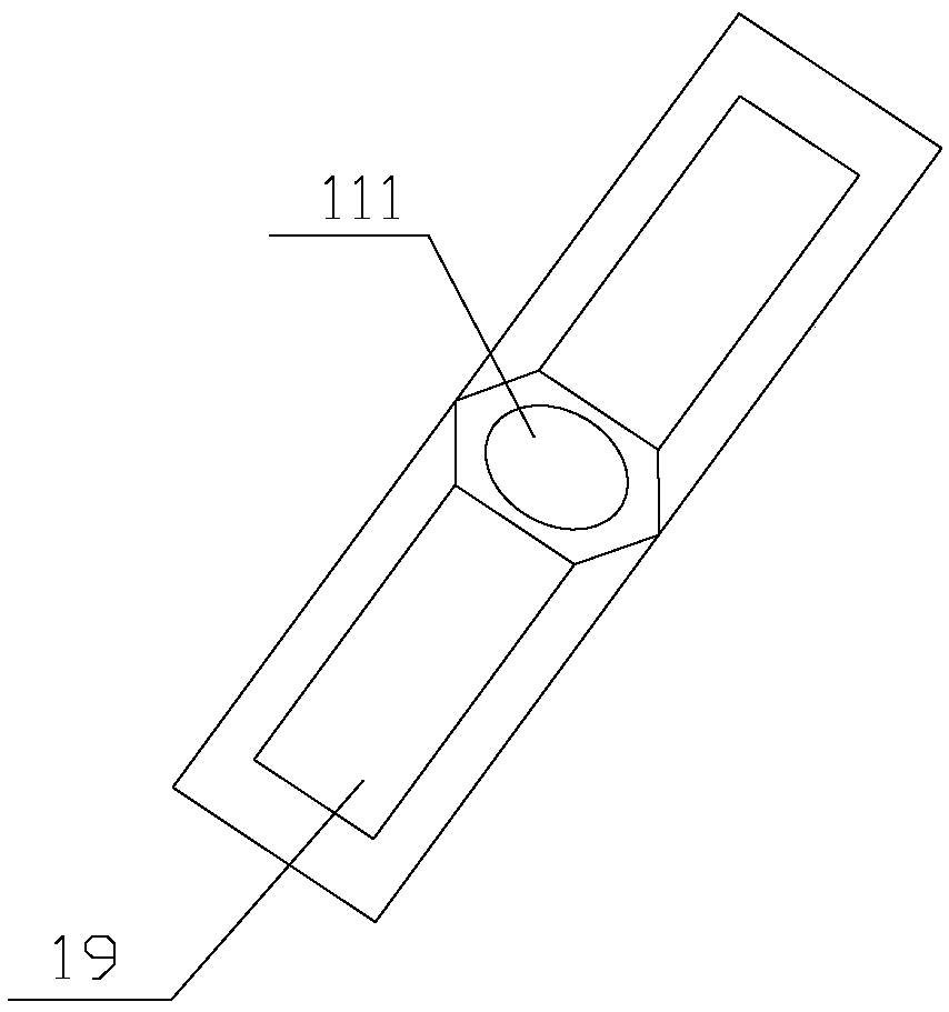
[0042] See attached Figure 11 In this embodiment, on the basis of Embodiment 1, the loading plate 31 is set to a conical shape, and the test box 5 is set to a cylindrical shape. On the bottom plate body of the loading plate 31, five first pressure probes are arranged along its diameter direction 24. On the cone of the loading plate 31, five reflective plates 23 on the same straight line as the first pressure probe 24 are arranged along the two symmetrical hypotenuses thereof; at the same time, on the top support 22 of the test box 5 Five displacement sensors 21 are set, and the positions of the displacement sensor 21, the reflection plate 23 and the first pressure probe 24 correspond one by one. The stress of the soil body was measured, and the strain states at these five different positions were measured, and the one-to-one correspondence between the stress and strain states of the soil at different positions on the same plane was realized.

[0043] See attached Figure 11...


PUM


Abstract

The invention provides a soil dynamic test device, and relates to the technical field of marine test equipment. The soil dynamic test device comprises a test box. Soil is paved on the bottom of the test box. Seawater is filled in the test box. A pressure measuring mechanism is arranged on the test box. A loading plate mechanism is connected to the upper part of the test box. The loading plate mechanism is connected to a circulation dynamic mechanism and a displacement measuring mechanism. The pressure measuring mechanism is connected to a computer control mechanism. The loading plate mechanismcomprises a plate body with a plane structure and a conical body arranged on the upper part of the plate body. The loading plate mechanism loads a pressure on a plane, the pressure on the middle of the plane is large, and the pressure on the periphery of the plane gradually decreases. A wave like (from wave peak to wave trough) loading effect is generated. The liquefaction situation of soil on asea bed is effectively simulated under the action of waves. The dynamic characteristics of the soil can be represented practically under the action of waves, the pore pressure and soil pressure of thesoil can be accurately measured during the liquefaction process, the operation is convenient, and the test device is practical and economic.

Description

technical field [0001] The invention relates to the technical field of marine testing equipment, in particular to a soil dynamic testing device. Background technique [0002] Larger wind and waves will liquefy the seabed. The liquefaction of the seabed caused by waves is one of the key issues that must be considered in coastal and offshore engineering. The stability analysis of the seabed under the action of waves is also in the design of submarine pipelines, breakwaters and offshore platform foundations. important content. Wave action causes the seabed to generate oscillating pore water pressure and residual pore water pressure. When the pore water pressure is too late to dissipate, the pore water pressure inside the seabed will accumulate, that is, the residual pore water pressure will rise, which will cause the effective stress of the soil to decrease and weaken the seabed. The shear strength of the bed soil even leads to liquefaction of the soil. The seabed soil liquef...

Claims


Application Information

Patent Timeline
Patent Type & Authority Applications(China)
IPC IPC(8): G01N3/34
CPCG01N3/34
Inventor 许国辉陈文浩任宇鹏
Owner OCEAN UNIV OF CHINA
Why Eureka
Try Eureka