
Brake device for vehicle

A technology of brake device and wheel brake cylinder, which is applied in the direction of brake transmission device, control device, braking action starting device, etc. discomfort, etc., for reliable and rapid detection

Active Publication Date: 2013-09-18
HONDA MOTOR CO LTD
View PDF8 Cites 9 Cited by
  • Summary
  • Abstract
  • Description
  • Claims
  • Application Information

AI Technical Summary

Problems solved by technology

[0008] However, when the electric motor falls off from the casing of the slave cylinder, or the gears of the reduction mechanism are damaged or poorly meshed and the motor idles, the slave cylinder may not be able to generate brake hydraulic pressure despite the rotation of the motor.
In this case, the control device cannot determine the abnormal state due to the rotation of the electric motor, and the switching from the braking based on the brake hydraulic pressure generated by the slave hydraulic cylinder to the braking based on the brake hydraulic pressure generated by the master hydraulic cylinder is delayed, May cause discomfort to the driver

Method used


Image

  • Brake device for vehicle
  • Brake device for vehicle
  • Brake device for vehicle

Examples


no. 1 approach

[0044] first embodiment

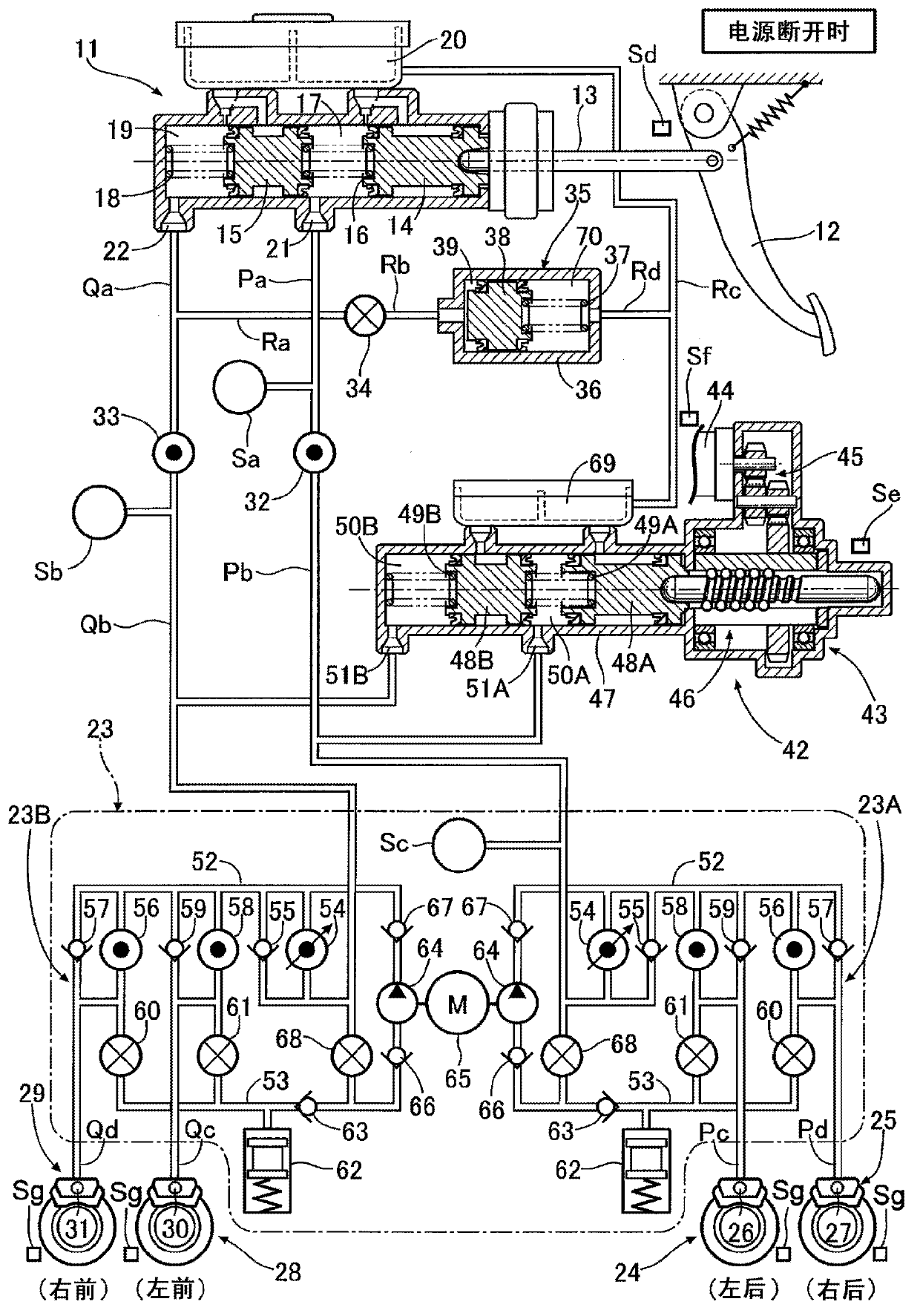
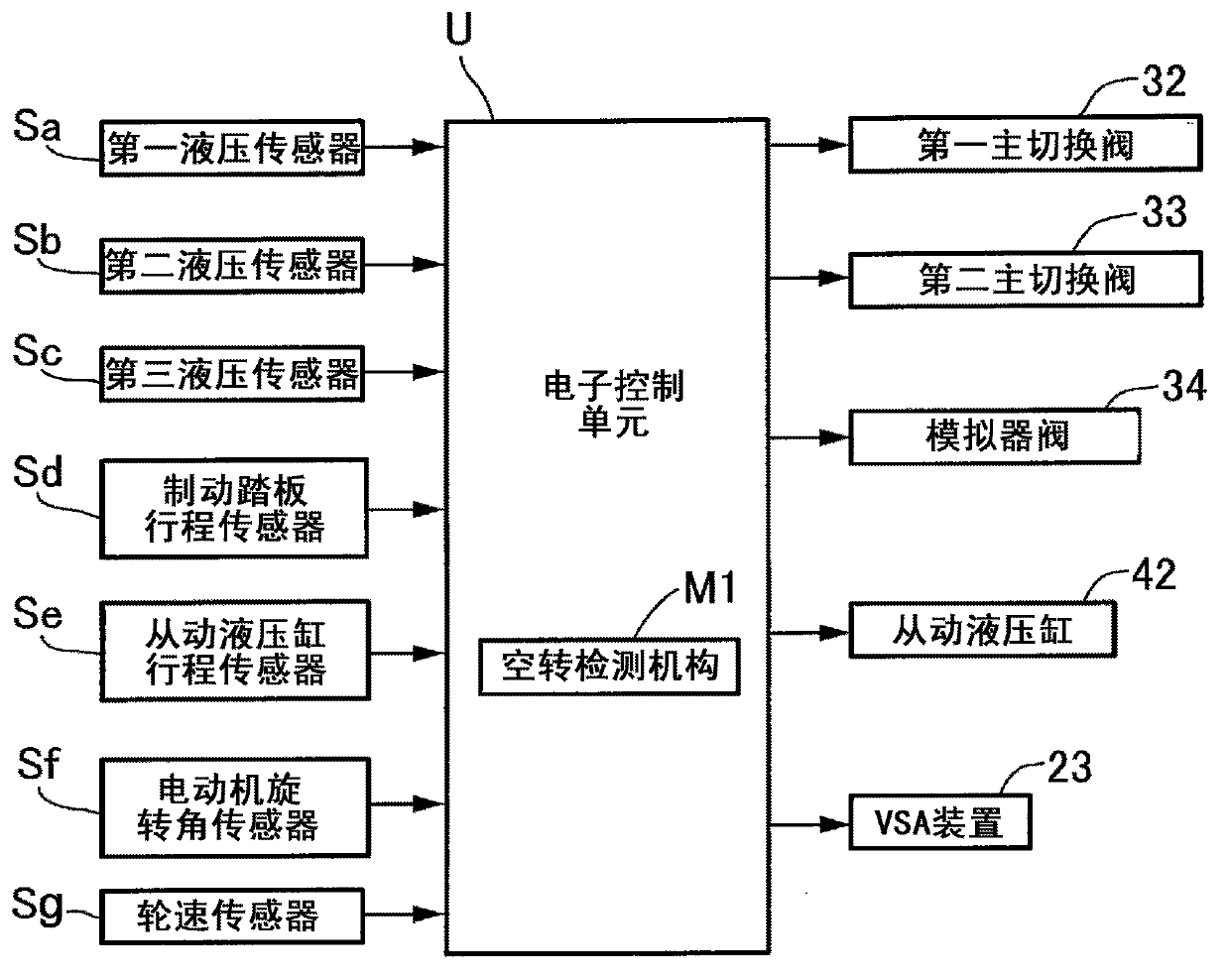
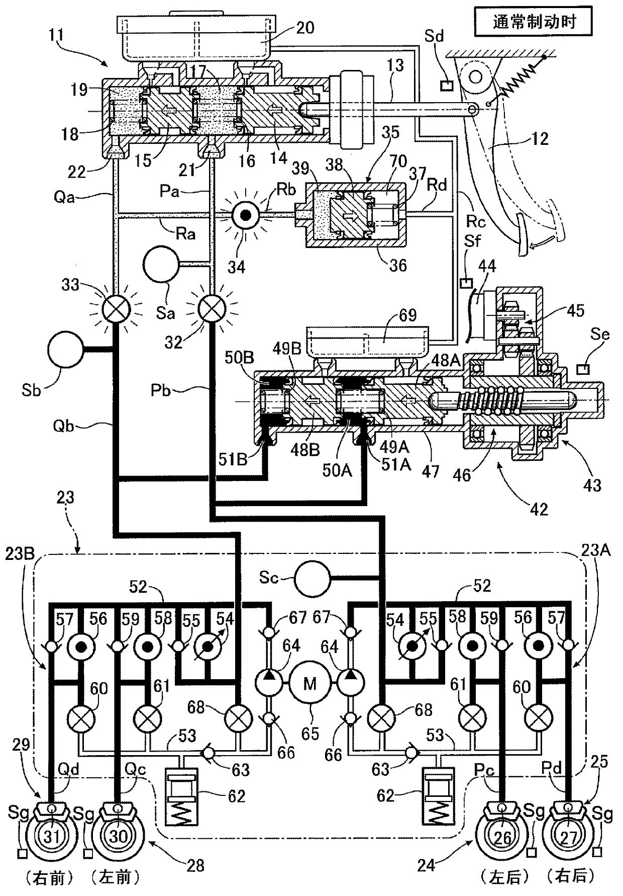
[0045] Such as figure 1 As shown, the tandem-type master hydraulic cylinder 11 has a first piston 14 connected to the brake pedal 12 operated by the driver via a push rod 13, and a second piston 15 arranged in front of the first piston 14. A first hydraulic chamber 17 containing the return spring 16 is defined between the piston 14 and the second piston 15 , and a second hydraulic chamber 19 containing the return spring 18 is defined in front of the second piston 15 . The first hydraulic chamber 17 and the second hydraulic chamber 19 , which can communicate with the reservoir 20 , respectively have a first output port 21 and a second output port 22 . The device 23 and the fluid paths Pc, Pd are connected to the wheel cylinders 26, 27 (first system) of the disc brake devices 24, 25 of the left and right rear wheels, for example, and the second output port 22 is connected via the fluid path Qa. , Qb, VSA device 23 and fluid passages Qc, Qd are connect...

no. 2 approach

[0084] The second embodiment differs from the first embodiment only in the function of the lost motion detection mechanism M1, and the other configurations are the same.

[0085] Figure 8 It is a map showing the relationship between the command voltage Vq and the torque current Iq of the motor 44 under vector control. When the motor 44 is not idling normally, as shown by the solid line, the torque current Iq increases at a fixed rate of increase with the increase of the indicated voltage Vq, and when the indicated voltage Vq further increases, the rate of increase of the torque current Iq decreases gradually . On the other hand, when the motor 44 is idling abnormally, as indicated by the dotted line, the torque current Iq increases at a fixed rate of increase that is significantly lower than that in the normal state as the indicated voltage Vq increases.

[0086] Thus, in Figure 8 In the map of , a hatched area is set in advance, and when the indicated voltage Vq and torq...


PUM


Abstract

A brake device wherein, when a malfunction occurs that renders a slave cylinder (42) inoperable, wheel cylinders (26, 27, 30, 31) are actuated by brake fluid pressure generated by a master cylinder (11), which is actuated by a brake pedal (12). When the rotational speed of a motor (44) of the slave cylinder (42) is greater than a standard value set according to the stroke of the slave cylinder (42), an idling detection means detects idling of the motor (44), making it possible to detect idling of the motor (44) reliably and quickly. When idling of the motor (44) is detected, a control means opens master cut valves (32, 33) and the wheel cylinders (26, 27, 30, 31) are actuated by brake fluid pressure generated by the master cylinder (11), thus enabling the inoperable slave cylinder (42) to be quickly backed up by the master cylinder (11).

Description

technical field [0001] The present invention relates to a kind of so-called BBW( brake-by-wire) type braking device. Background technique [0002] In the above-mentioned BBW brake device, a slave hydraulic cylinder that generates brake fluid pressure by operating an electrical signal corresponding to the amount of operation of the brake pedal is a hydraulic cylinder that is slidably fitted to a piston of the hydraulic cylinder. , an electric motor, and a deceleration mechanism that decelerates the rotation of the electric motor to convert it into reciprocating motion of the piston, which is known from Patent Document 1 below. [0003] prior art literature [0004] patent documents [0005] Patent Document 1: Japanese Patent Laid-Open No. 2005-343366 [0006] Summary of the invention [0007] The problem to be solved by the invention [0008] However, if the motor falls off the casing of the slave cylinder, or the gears of the speed reduction mechanism are damaged or po...

Claims


Application Information

Patent Timeline
Patent Type & Authority Applications(China)
IPC IPC(8): B60T13/12B60T8/92B60T13/66B60T13/74B60T17/22B60T8/17
CPCB60T8/4081B60T13/662B60T13/745B60T17/221B60T2270/402B60L2240/421B60L2240/461B60L2250/26B60T7/042B60T17/223B60T2270/82B60T2270/40B60T13/146Y02T10/64B60T15/00
Inventor 帆谷雄辉大久保直人伊藤雄贵
Owner HONDA MOTOR CO LTD
Learn More