
Auto focusing mechanism of surveying instrument

A measuring machine and focus technology, which is used in measuring devices, measuring instruments, mapping and navigation, etc., can solve the problems of deterioration of AF accuracy, longer AF processing time, and adverse effects on measurement results, and achieves rapid and accurate detection. Effect

Active Publication Date: 2006-08-30
KK TOPCON
View PDF2 Cites 4 Cited by
  • Summary
  • Abstract
  • Description
  • Claims
  • Application Information

AI Technical Summary

Problems solved by technology

[0008] That is, in the case of processing the output signal of the line sensor 24, if an arithmetic process of calculating the pitch of the pattern on the scale is performed based on erroneous data or data with a low signal level, errors in distance measurement results, Or the problem of deterioration of ranging accuracy
[0009] As a result, autofocus, which is a process for automatically focusing the telescope 20 on the scale, fails, so that the processing time of autofocus becomes longer, the operation efficiency is reduced, or the precision of autofocus is deteriorated to cause measurement failure. Results are badly affected

Method used


Image

  • Auto focusing mechanism of surveying instrument
  • Auto focusing mechanism of surveying instrument
  • Auto focusing mechanism of surveying instrument

Examples


Embodiment Construction

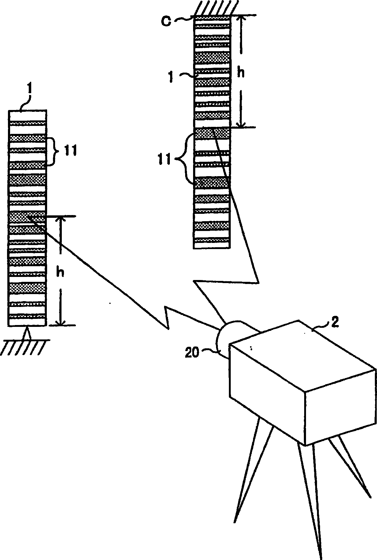
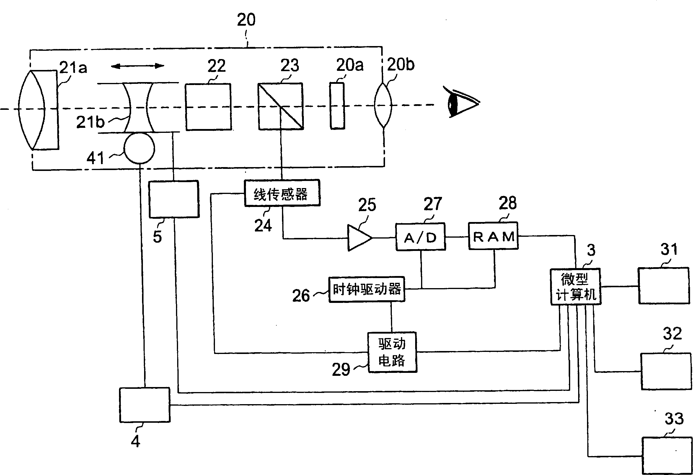
[0037] Hereinafter, embodiments of the present invention will be described based on examples. figure 1 It is a perspective view for explaining the relationship between the electronic level and the scale to which the present invention is applied, figure 2 It is a block diagram showing an automatic focus mechanism of a measuring machine according to an embodiment of the present invention.

[0038] In these figures, the electronic level 2 is configured as a measuring machine for leveling the scale 1 with a telescope 20 and measuring the height h of the leveling position. On the scale 1 , a plurality of black marks 11 are displayed at equal intervals along the vertical direction (axis direction) of the scale 1 on the surface of the white background. The width dimension in the vertical direction of each mark 11 is not completely the same size, and marks 11 of various sizes are arranged on the scale 1 in a predetermined order. That is, on the scale 1, a plurality of patterns for...


PUM


Abstract

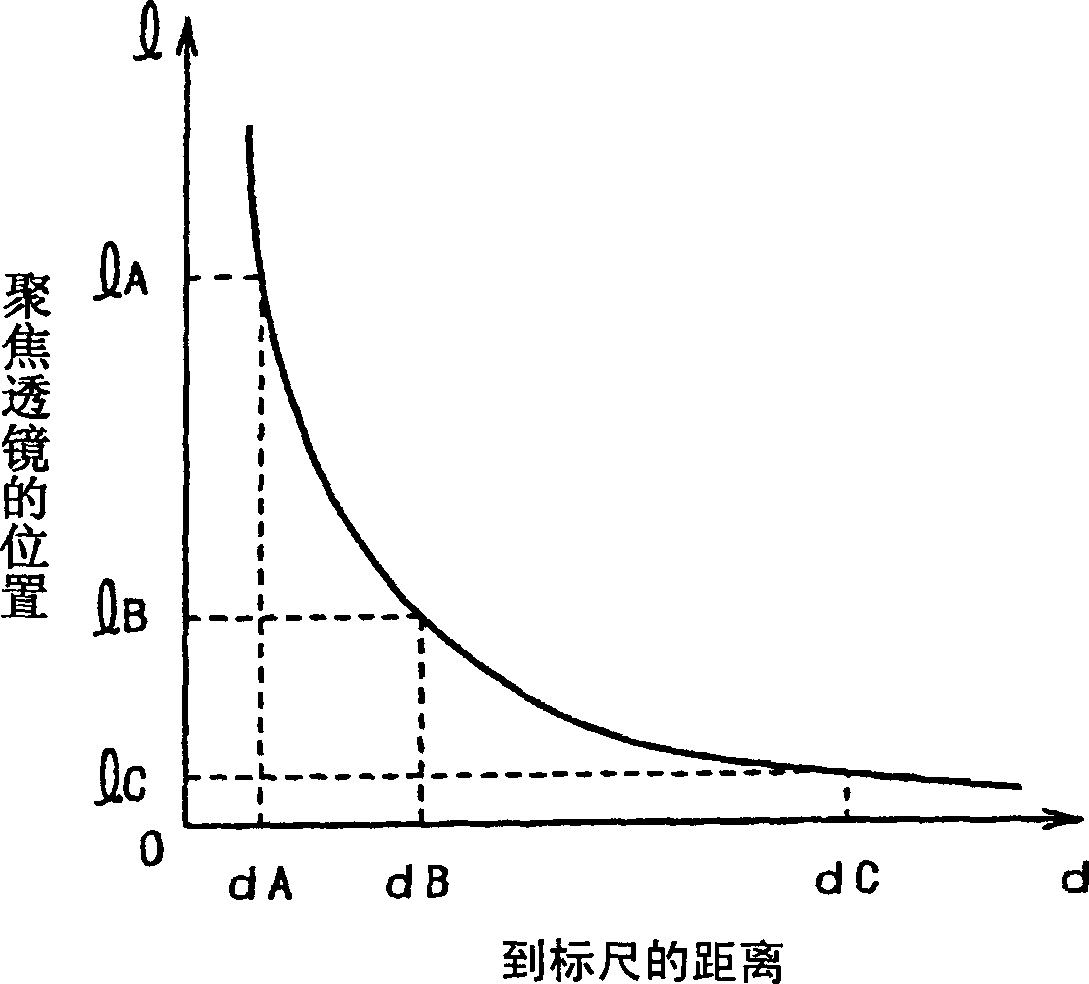
The invention is able to detect that a focusing lens is positioned on a focusing position surely and quickly. In a step for moving the focusing lens 21b by a motor 41 along an optical axis of a collimation optical system, an object image following collimation of a telescope 20 is converted into an electric signal by a line sensor 24, and an output signal from the line sensor 24 is converted into a digital signal by an A / D converter 27 and stored in a RAM 28, and the frequency of the electric signal by the output from the line sensor 24 is monitored in a microcomputer 3 based on data stored in the RAM 28. In a step wherein the position of the focusing lens 21b is changed, when a specific frequency correlated with the position of the focusing lens 21b is detected, the distance from the telescope 20 to a staff 1 is determined based on the output signal from the line sensor 24 by assuming that the focusing lens 21b is positioned approximately on the focusing position, and the focusing lens 21b is positioned on the focusing position from the distance and the position of the focusing lens 21b by the output from a position sensor 5.

Description

technical field [0001] The present invention relates to an automatic focus mechanism of the measuring machine, which is installed on a measuring machine such as an electronic level with a telescope for parallelizing the scale, and can automatically align the focus of the telescope with the scale. Background technique [0002] As an automatic focus mechanism installed on an electronic level, for example, there are Figure 10 , Figure 11 mechanism shown (see Patent Document 1). The automatic focus mechanism is installed on the telescope 20 as a horizontal correction optical system, and the telescope 20 has an automatic compensation mechanism 22 of an objective lens 21a, a focusing lens 21b, a horizontal correction axis, a beam splitter 23, a focus plate 20a, and an eyepiece 20b, This automatic focus mechanism has a stepping motor 41 for moving the focus lens 21b along the optical axis of the horizontal optical system, a drive circuit 4 for controlling the driving of the step...

Claims


Application Information

Patent Timeline
Patent Type & Authority Applications(China)
IPC IPC(8): G02B7/28
CPCG01C15/00G02B7/36
Inventor 西田信幸东海林直树长尾崇司
Owner KK TOPCON
Learn More