
Method for improving shear strength of nonmetal anti-floating anchor

Active Publication Date: 2013-09-18
QINGDAO TECHNOLOGICAL UNIVERSITY
View PDF7 Cites 11 Cited by
  • Summary
  • Abstract
  • Description
  • Claims
  • Application Information

AI Technical Summary

Problems solved by technology

However, due to the high price of corrosion-resistant low-alloy materials and the difficulty of smelting, it is not easy to adopt from an economic point of view; the anti-corrosion treatment and cathodic protection of the bolt surface adopt isolation and insulation protection measures, and the materials used may affect the anchorage strength of steel bolts. And the grip strength is greatly affected, or the cost is high, and the anti-corrosion effect is not ideal
For urban traffic construction such as subways, the stray current generated by the DC power supply system cannot fundamentally solve the electrochemical corrosion of metal anchors; the use of non-metallic materials can effectively avoid the corrosion of anti-floating anchors. Metal anti-floating anchors mostly use glass fiber reinforced polymer (GFRP) as the reinforcement material. Although this non-metallic material can effectively prevent the anti-floating anchors from being corroded, since the GFRP material is an anisotropic material, its transverse shear resistance The strength is far lower than its tensile strength. At the interface between the inner anchorage section and the outer anchorage section of the non-metallic anti-floating anchor, horizontal shear force will inevitably be generated due to construction technology and other reasons, resulting in the inner and outer anchorage of the anchor. The interface of the anchorage section is damaged by shearing, and its tensile strength cannot be fully exerted, thus failing to achieve its purpose of anti-floating

Method used


Image

  • Method for improving shear strength of nonmetal anti-floating anchor
  • Method for improving shear strength of nonmetal anti-floating anchor
  • Method for improving shear strength of nonmetal anti-floating anchor

Examples


Embodiment

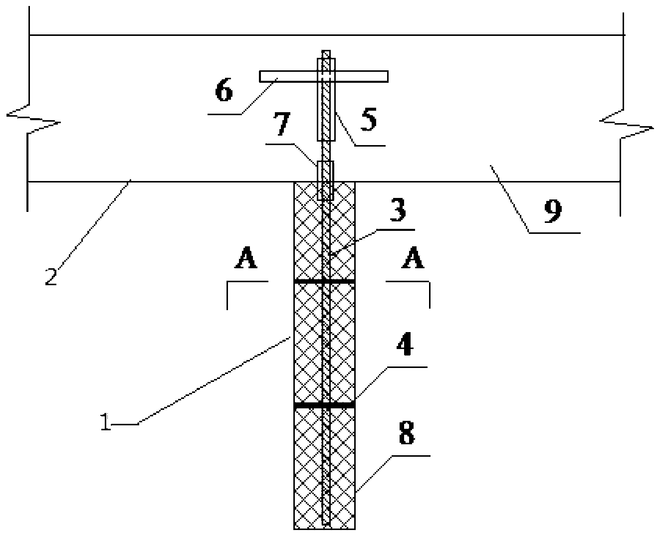
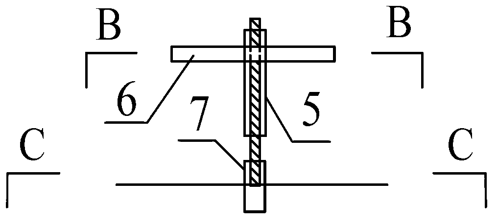
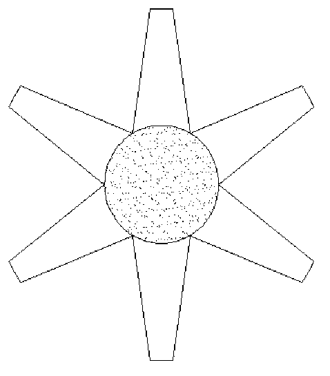
[0022] In this embodiment, first, according to the size requirements of the non-metallic anti-floating anchor, holes are drilled on the rock foundation to form the anchor hole 8, and the anchor hole 8 is as vertical as possible to the ground; the centering device 4 is installed at a certain distance. The distance between the outer surface of the anchor body 3 should be determined according to the length of the anchor section in the anchor body 3; the rigid arm 7 is inserted into the anchor body 3, and the rigid arm 7 is tightly bonded to the anchor body 3 through epoxy resin. The rigid arm 7 is fixed at the interface between the inner anchor section and the outer anchor section of the anchor body 3, and the dimensions of the inner and outer anchor sections of the rigid arm 7 are the same; insert the anchor rod with the centering device 4 and the rigid arm 7 into the anchor rod In the hole 8, feed it manually until the bottom end of the anchor rod reaches the bottom of the ancho...


PUM


Abstract

The invention belongs to the technical field of anti-floating anchors of building construction, and relates to a method for improving the shear strength of an interface of an inner anchorage section and an outer anchorage section of a nonmetal anti-floating anchor. According to the method, a steel arm is additionally mounted on an anchor body, at the inner anchorage section and the outer anchorage section, of the nonmetal anti-floating anchor, is a seamless steel pipe, and is tightly connected with the anchor and a bottom plate of a building (structure) at the outer anchorage section, tightly connected with the anchor and mortar at the inner anchorage section, and tightly bonded on the outer side of a GFRP (Glass Fiber Reinforced Polymer) anchor; since the rigidity of the seamless steel pipe is higher, the defect of lower transverse shear strength of the GFRP anchor is overcome; the steel arm can provide the sufficient transverse shear strength under the action of horizontal load; and therefore, the purpose of limiting the transverse shear deformation of the GFRP anchor is achieved. The method is simple to operate, low in cost, high in reliability, and good in economic benefit, and has prominent substantial characteristics and significant progress, required devices are simple and easy to obtain, and the mounting and construction are convenient.

Description

Technical field: [0001] The invention belongs to the technical field of anti-floating anchor rods for building construction, and relates to a method for increasing the shear strength at the interface between inner and outer anchor sections of a non-metallic anti-floating anchor rod. Background technique: [0002] With the development and utilization of urban underground space, the buried depth of building foundations continues to increase, and the problem of anti-floating has become more and more prominent. Bolts have the advantages of strong stratum adaptability, distributed stress, convenient construction, cost saving, etc., especially in hard rock and soil layers with large bearing capacity, which has more advantages. The basic principle is to bury the anchor rod in the ground, and use the tensile force generated by the tensile strength of the anchor rod itself and the pull-out force generated by the friction between the anchor rod and the rock-soil layer to control the f...

Claims


Application Information

Patent Timeline
IPC IPC(8): E02D5/74
Inventor 张明义白晓宇闫楠寇海磊郭燕文汤洪霞李伟伟
Owner QINGDAO TECHNOLOGICAL UNIVERSITY
Learn More