
Terminal tongue and manufacturing method thereof

A manufacturing method and tab technology, which is applied in the fields of final product manufacturing, sustainable manufacturing/processing, hybrid/electric double layer capacitor manufacturing, etc., can solve problems such as short circuit and inability to ensure insulation, and achieve the effect of high-efficiency manufacturing

Inactive Publication Date: 2013-09-11
SHOWA DENKO PACKAGING CO LTD
View PDF7 Cites 12 Cited by
  • Summary
  • Abstract
  • Description
  • Claims
  • Application Information

AI Technical Summary

Problems solved by technology

[0014] However, if such stricter heat-sealing conditions are adopted than conventional ones, a short circuit is likely to occur between the metal plate of the tab and the metal layer of the outer package, resulting in a problem that sufficient insulation cannot be ensured.

Method used


Image

  • Terminal tongue and manufacturing method thereof
  • Terminal tongue and manufacturing method thereof
  • Terminal tongue and manufacturing method thereof

Examples


Embodiment 1

[0134] Prepare a metal plate (length 50 mm x width 50 mm) 2 formed by applying 2 μm thick nickel plating on the surface of a 200 μm thick copper plate, and two resin insulating films 11, 70 mm long x 10 mm wide x 100 μm thick. 12 (see Figure 4 ).

[0135] In addition, a pair of upper and lower heated and pressurized molds 30 are prepared. The heated and pressurized molds 30 are laminated and integrated with a substantially plate-shaped metal hard body 31 by laminating resin sheets 33 made of fluorinated vinyl resin with a rubber hardness of 60 degrees. formed on one side (see Figure 4 ). On the non-laminated surface of the resin sheet 33 (the surface that comes into contact with the insulating film during hot pressing), a concave portion 34 having substantially the same shape as the insulating film in plan view is formed.

[0136] Next, the above-mentioned insulating films 11 and 12 are placed on both sides of the above-mentioned metal plate 2 so as to cover a part of the...

Embodiment 2

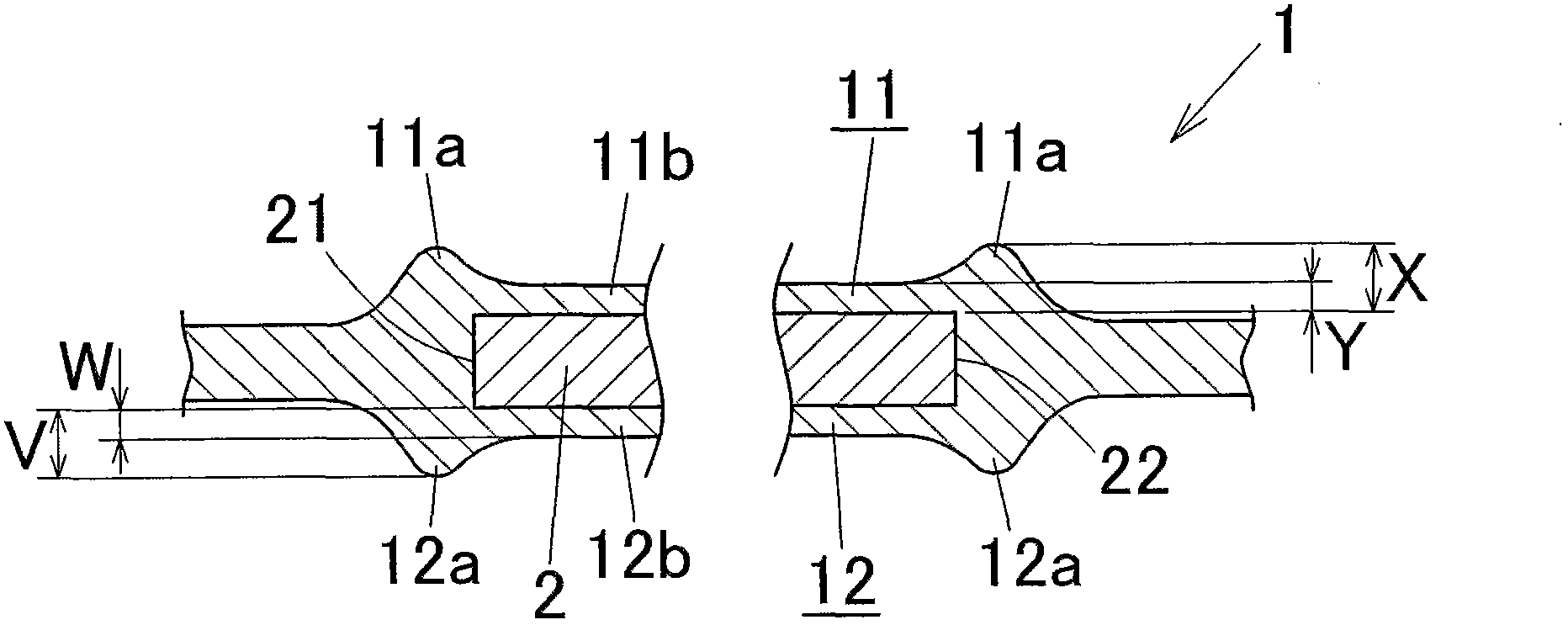
[0139] The temperature of the heating and pressing mold during hot pressing is 210°C, the pressing pressure applied by the heating and pressing mold is 1000N, and the hot pressing time is set to 7 seconds, except that it is the same as Example 1, thus obtaining image 3 Tab 1 of the structure shown.

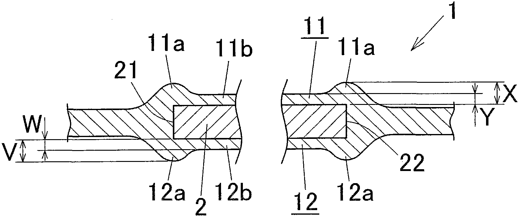
[0140] An optical microscope photograph of the cross-section of the obtained tab 1 was taken, and the enlarged image revealed that the first swelling rate was 50%, and the second swelling rate was 50%.

Embodiment 3

[0142] The temperature of the heating and pressing mold during hot pressing is 240° C., the pressing pressure applied by the heating and pressing mold is 1000 N, and the hot pressing time is set to 7 seconds, except that it is the same as Example 1, thus obtaining image 3 Tab 1 of the structure shown.

[0143] An optical microscope photograph of the cross-section of the obtained tab 1 was taken, and the enlarged image showed that the first swelling rate was 90%, and the second swelling rate was 90%.


PUM

PropertyMeasurementUnit
Rubber hardnessaaaaaaaaaa

Abstract

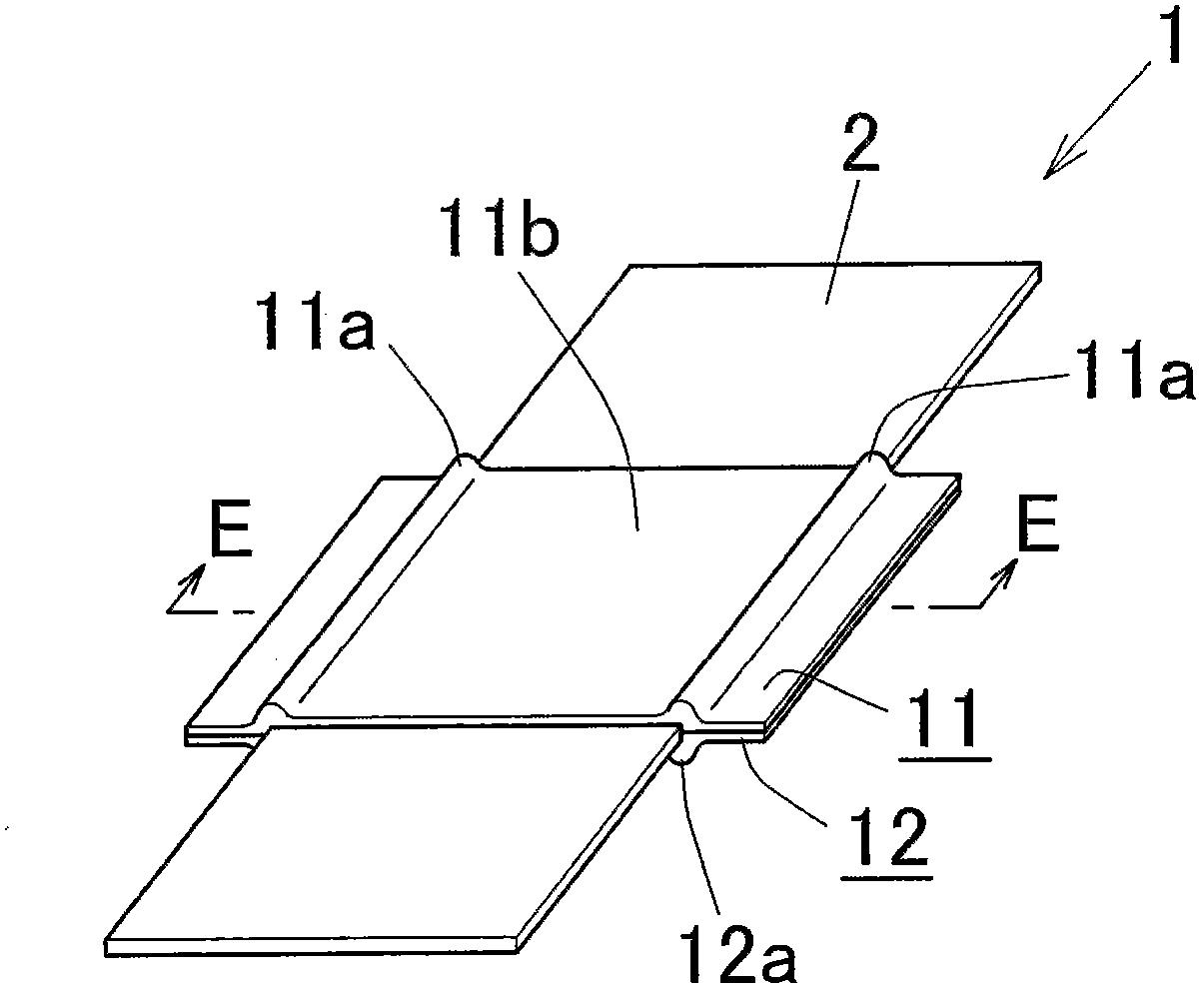
The invention provides a terminal tongue comprising that first and second resin insulation films (11, 12) are adhered on respective surfaces of a portion of a metal plate (2) in a longitudinal direction of the plate; both end sections of the first insulation film and both end sections of the second insulation film are integrally welded with one another; in the first insulation film (11) and the second insulation film (12), first and second projection portions (11a, 12a) are formed at regions of two ends (21, 22) of the plate (2) in a width direction and regions corresponding to areas near the two ends (21, 22) of the plate (2) in the width direction. The projection portions are protruded outward in thickness directions of the first and the second films, respectively. Even under a condition that an outer packaging body is performed heat sealing through a strict heat sealing condition, the terminal tongue cannot generate short circuit and sufficient insulation properties can be ensured.

Description

[0001] This application claims priority based on Japanese Patent Application Japanese Patent Application No. 2012-43643 filed on February 29, 2012, and the disclosure thereof directly constitutes a part of the present application. technical field [0002] The present invention relates to tab leads that are suitable, for example, as tabs for secondary batteries such as lithium ion secondary batteries and tabs for electrochemical devices such as electric double-layer capacitors. [0003] In addition, in this specification and claims, regarding a metal plate, the term "longitudinal direction" refers to the direction in which both ends of the metal plate not covered with an insulating film are connected to each other, and regarding a metal plate, "width The term "direction" refers to a direction perpendicular to the aforementioned longitudinal direction within the plane of the metal plate. [0004] In addition, in this specification and a claim, the term "aluminum" is used in the ...

Claims


Application Information

Patent Timeline
IPC IPC(8): H01M2/26H01G11/74H01G11/84H01M50/178H01M50/533H01M50/534H01M50/553H01M50/562H01M50/571
CPCH01M10/0525H01M10/0585H01G11/80H01G11/74Y02E60/10H01M50/571Y02P70/50H01M50/178H01M50/562H01M50/534H01M50/553H01M50/533B29C66/83221B29C66/1122B29C66/433B29L2031/3468B29C66/81431B29C66/81425B29C66/81264B29C65/18B29C66/919B29C66/929B29C66/949B29C66/81457B29C66/8122B29C66/81261B29C66/72321B29C66/73921B29K2705/02B29K2705/10B29C66/7352B29C66/71B29C65/8253B29K2883/00B29K2827/12B29K2023/12B29K2023/06H01M50/543H01M50/183Y02E60/13
Inventor 畑浩渡边拓郎
Owner SHOWA DENKO PACKAGING CO LTD
Learn More