Eureka AIR delivers breakthrough ideas for toughest innovation challenges, trusted by R&D personnel around the world.

The Method of Quickly Realizing the Graphical Control System of Matrix Switch

A matrix switch and control system technology, applied in the direction of multi-programming devices, etc., can solve problems such as unfavorable product upgrades, affecting development progress, and heavy workload of redevelopment, so as to reduce the difficulty of development and maintenance, lower the technical threshold, and reduce The effect of maintenance costs

Active Publication Date: 2016-09-07
CHINA ELECTRONIS TECH INSTR CO LTD
View PDF7 Cites 0 Cited by
  • Summary
  • Abstract
  • Description
  • Claims
  • Application Information

AI Technical Summary

Problems solved by technology

[0005] like figure 1 As shown, the existing matrix switch graphical control system includes a system interface design module, a switch business function module, and a graphical realization module. In this traditional development method, the system interface design module, the switching business function module, and the graphical realization module are interactive Because there is no separation between the modules, there is a large dependence on each other. Therefore, after the switch hardware is modified or upgraded, it may lead to large-scale modifications of the other two modules, which is not conducive to product upgrades; for new switch products When developing a graphical control system, because there are very few parts available for borrowing, basically all of them need to be redeveloped, so the workload of redevelopment is very heavy, which seriously affects the development progress

Method used


Image

  • The Method of Quickly Realizing the Graphical Control System of Matrix Switch
  • The Method of Quickly Realizing the Graphical Control System of Matrix Switch
  • The Method of Quickly Realizing the Graphical Control System of Matrix Switch

Examples


Embodiment Construction

[0028] The technical scheme of the present invention will be described in further detail below in conjunction with the application of the present invention in the matrix switch (such as AV6941 matrix switch) graphical control system of the 41st Research Institute of China Electronics Technology Group Corporation.

[0029] Because there is this close relationship between the graphical control system and the business functions of the switch product, although the graphical part does not directly involve the business of the switch module itself in the present invention, it is closely related to the attribute information of the matrix switch product, so the graphical module And business function modules must have good versatility to meet the diverse needs.

[0030] The present invention abstracts a general matrix switch function interface by analyzing the general functional characteristics of the matrix to meet the requirements of versatility and adaptability to diversification. Th...


PUM


Abstract

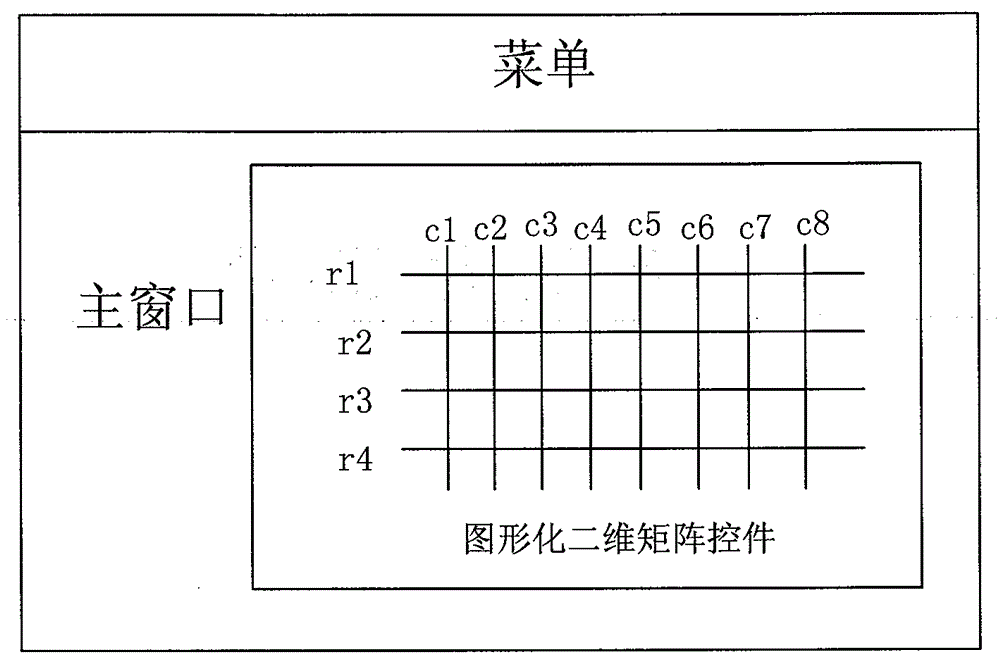
The invention discloses a method for rapid implementation of a matrix switch graphical control system. The method adopts a switch control middleware, a graphical matrix control and a switch driving program, and comprises the following steps: performing operation environment configuration, and using the graphical matrix control and the switch control middleware to build a general system frame; defining a general matrix switch functional interface, wherein switch driving programs of matrix switches realize the function of definition of the general matrix switch functional interface, and using the general system frame to load the switch driving program to generate the matrix switch graphical control system; utilizing the switch control middleware to realize the processes of obtaining switch topology information from the switch driving program and building a two-dimensional graphical matrix; and utilizing the switch control middleware to realize the process of performing switch module operation via mouse operation on the two-dimensional graphical matrix. According to the invention, the development and maintenance difficulties of the matrix switch graphical control system are reduced, and the development cycle of a new product is shortened.

Description

technical field [0001] The invention relates to computer information system construction technology and computer image data processing technology, in particular to a method for quickly realizing a matrix switch graphic control system. Background technique [0002] The microwave switch is the center of signal transmission and distribution in the microwave automatic test system. Using the microwave switch matrix can make full use of test resources, reduce the workload of switching various instruments, prolong the service life of the instrument, and improve the test efficiency. As new products are introduced, the complexity of the device under test continues to grow, resulting in a dramatic increase in the number of test points that must be connected. The sharp increase in the number of test points also means a sharp increase in the complexity of the switch, so that the upgrade of existing switch products or the development of new switch products will become more and more urgen...

Claims


Application Information

Patent Timeline
IPC IPC(8): G06F9/46
Inventor 吴波方葛丰宋斌刘毅邱田华方鹏
Owner CHINA ELECTRONIS TECH INSTR CO LTD
Why Eureka
Eureka Blog
Learn More