Non-contact testing system and method for rfid tag antenna

An RFID tag, non-contact technology, applied in the direction of measuring electricity, measuring devices, measuring electrical variables, etc., can solve the problems of easy eye fatigue, inability to measure electrical properties, and increased chip loss rate, to avoid unreliable contact and achieve Effects of automated inspections, reduced accuracy requirements

Active Publication Date: 2015-08-12
SUZHOU ZUENS IOT TECH CO LTD
View PDF7 Cites 0 Cited by
  • Summary
  • Abstract
  • Description
  • Claims
  • Application Information

AI Technical Summary

Problems solved by technology

Manual visual inspection has the following disadvantages: the visual inspection method has a high work intensity for the inspectors; the eyes are prone to fatigue; the rate of false detection and missed detection is high; the inspection efficiency is low
Machine vision has the following deficiencies: it cannot measure the electrical performance; it requires high resolution of the camera, especially when the antenna line width or line spacing is small; it cannot measure the connection impedance of the stamping bridge; it is difficult to identify the overlapping parts of the aluminum foil
The measurement after bonding the chip has the following shortcomings: the loss rate of the chip is increased, because the chip price is high, and the waste caused by the bad antenna far exceeds the price of the antenna itself
Probe instrument detection has the following deficiencies: the impedance of the probe itself, the contact impedance of the probe, and the output impedance of the instrument affect the test results; for the aluminum antenna, the dense oxide layer on the surface is likely to cause poor contact of the probe; Needle positioning is difficult; it is easy to leave unsightly traces at the contact position of the probe and affect the appearance of the antenna; the high positioning requirements affect the efficiency of the test, and the cost of the precise positioning mechanism is high

Method used


Image

  • Non-contact testing system and method for rfid tag antenna
  • Non-contact testing system and method for rfid tag antenna
  • Non-contact testing system and method for rfid tag antenna

Examples


Embodiment 1

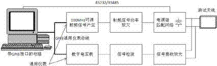
[0041] The antenna under test is an RFID high-frequency (HF) antenna, and a computer with a GPIB general instrument interface bus is used as a control and display unit. The computer communicates with the RF signal generator and digital voltmeter that also have a GPIB interface through the GPIB bus.

[0042] The RF signal generator and the digital voltmeter are connected to the computer via the GPIB cable to receive program-controlled commands and send data to the computer. The computer sends instructions to the RF signal generator through the GPIB bus to generate RF signals of specified frequency and amplitude.

[0043] The broadband radio frequency signal power amplifier amplifies the power of the signal generated by the radio frequency signal generator. The computer controls the tuning and matching circuit through the serial communication port to make the antenna resonant frequency the same as the frequency of the radio frequency signal generator. The tuning and matching circ...

Embodiment 2

[0049] The antenna under test is an RFID ultra-high frequency (UHF) antenna, and a computer with a GPIB universal instrument interface bus is used as a control and display unit. The computer communicates with a microwave radio frequency signal generator and a digital voltmeter that also have a GPIB interface through the GPIB bus.

[0050] The microwave radio frequency signal generator and the digital voltmeter are connected to the computer through the GPIB cable to receive program-controlled commands and send the data to the computer. The computer sends instructions to the microwave radio frequency signal generator through the GPIB bus to generate high-frequency signals of specified frequency and amplitude. Broadband microwave radio frequency The signal power amplifier amplifies the power of the signal generated by the microwave radio frequency signal generator. The computer controls the tuning matching circuit through the serial communication port to make the antenna resonant f...

Embodiment 3

[0056] The antenna under test is an RFID high-frequency (HF) antenna, and the microprocessor (MCU) is used as the central control unit to control the work of each module. The TTF liquid crystal display is connected to the microprocessor (MCU) to display data through the SPI, I2C or RS232 communication port. , Test results, SD memory card connected to the microprocessor for storing test data and configuration data.

[0057] Microprocessor (MCU) through SPI, I 2 C or parallel port controls the direct digital synthesis (DDS) radio frequency signal generator module to generate a specified frequency signal, the broadband radio frequency signal power amplifier amplifies the power of the radio frequency signal generated by direct digital synthesis (DDS), and the microprocessor (MCU) controls the digital-analog ( The D / A) conversion module outputs a precise voltage used as a bias for the varactor diode to tune the antenna at the frequency of the Direct Digital Synthesis (DDS) RF signa...


PUM


Abstract

The invention discloses a non-contact test system and method of an RFID label antenna. The non-contact test system of the RFID label antenna comprises a display unit, a data processing and controlling unit, a radio-frequency signal transmit / receive unit, a feed mechanism unit and a test antenna unit. The data processing and controlling unit is connected with the display unit, the radio-frequency signal transmit / receive unit and the feed mechanism unit in sequence, and the test antenna unit is connected with the radio-frequency signal transmit / receive unit. Due to the fact that non-contact test is adopted, test can be carried out free of requirement of binding a chip, dissipation of the chip is reduced, and working strength of testing personnel is reduced; the fault testing rate and the leak testing rate are low; automatic testing can be achieved, and testing efficiency is high; indirect measurement to electrical property can be achieved. The non-contact test system and method of the RFID label antenna can achieve automatic test and greatly reduces demands for mechanical mechanisms, and are very suitable for large-batch production testing.

Description

technical field [0001] The invention relates to the technical field of radio frequency identification technology testing, in particular to a system and method for testing RFID tag antennas. Background technique [0002] The full name of RFID is Radio Frequency Identification (Radio Frequency Identification), which is a non-contact automatic identification technology realized by radio frequency technology. RFID tags have the characteristics of small size, fast reading and writing speed, various shapes, long service life, reusability, large storage capacity, and ability to penetrate non-conductive materials. Combining with RFID readers can realize multi-target identification and mobile target identification , Further, through the combination with Internet technology, it can also realize the tracking of items and the sharing of information on a global scale. RFID technology is used in logistics, manufacturing, public information services and other industries, which can greatly...

Claims


Application Information

Patent Timeline
Patent Type & Authority Patents(China)
IPC IPC(8): G01R31/00
Inventor 陆凤生蔡雄辉
Owner SUZHOU ZUENS IOT TECH CO LTD
Why Eureka
Try Eureka