
A simulation design method for the spacing between boreholes based on the representative temperature of the borehole wall

A technology of simulation design and spacing, which is used in calculations, special data processing applications, instruments, etc., and can solve problems such as slow calculation speed and inability to directly analyze the influence of the heat transfer process of borehole spacing.

Inactive Publication Date: 2016-01-20
BEIJING UNIV OF TECH
View PDF2 Cites 0 Cited by
  • Summary
  • Abstract
  • Description
  • Claims
  • Application Information

AI Technical Summary

Problems solved by technology

Although this modeling method can accurately solve the representative temperature of the hole wall, the calculation speed is slow, and it is impossible to directly analyze the influence of the hole spacing on the heat transfer process
Both in the solution of the hole wall temperature and the design of the ground source heat exchanger have great limitations

Method used


Image

  • A simulation design method for the spacing between boreholes based on the representative temperature of the borehole wall
  • A simulation design method for the spacing between boreholes based on the representative temperature of the borehole wall
  • A simulation design method for the spacing between boreholes based on the representative temperature of the borehole wall

Examples


Embodiment Construction

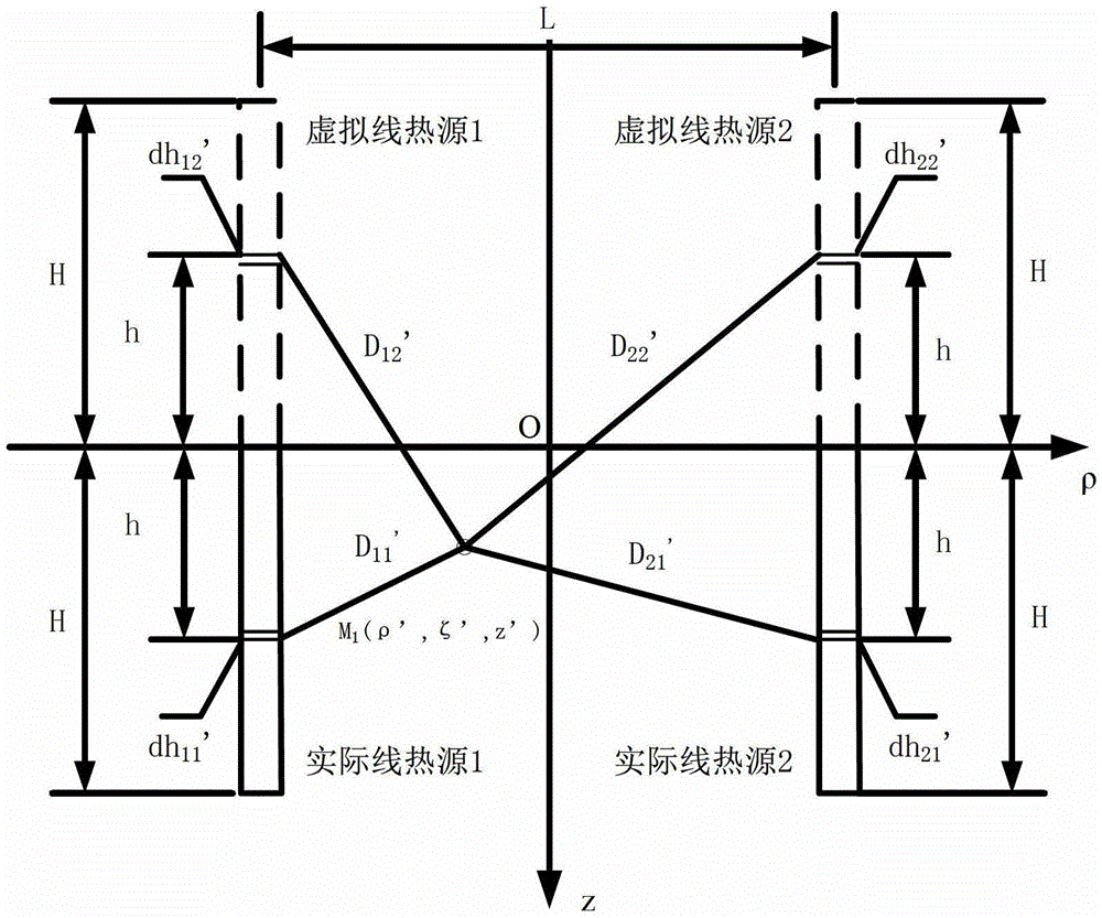
[0094] Based on the principle of finite long-line heat source, the invention establishes the heat transfer model outside the hole with double boreholes and four boreholes in the cylindrical coordinate system, and analyzes the influence of the change of borehole spacing on the representative temperature of the hole wall. The representative temperature of the hole wall is a key parameter in engineering calculations. Substituting it into the heat transfer model in the borehole can solve the outlet temperature. In order to simplify the calculation process, the one-dimensional heat transfer model in the borehole is commonly used to estimate the temperature response of the borehole wall. The physical equations are as follows:

[0095] T f =T b +QR b (1)

[0096] T outlet = 2T f -T inlet (2)

[0097] where T f1 is the average temperature of the fluid, T b is the representative temperature of the hole wall, Q is the exothermic intensity of the U-shaped tube, R b is the tota...


PUM


Abstract

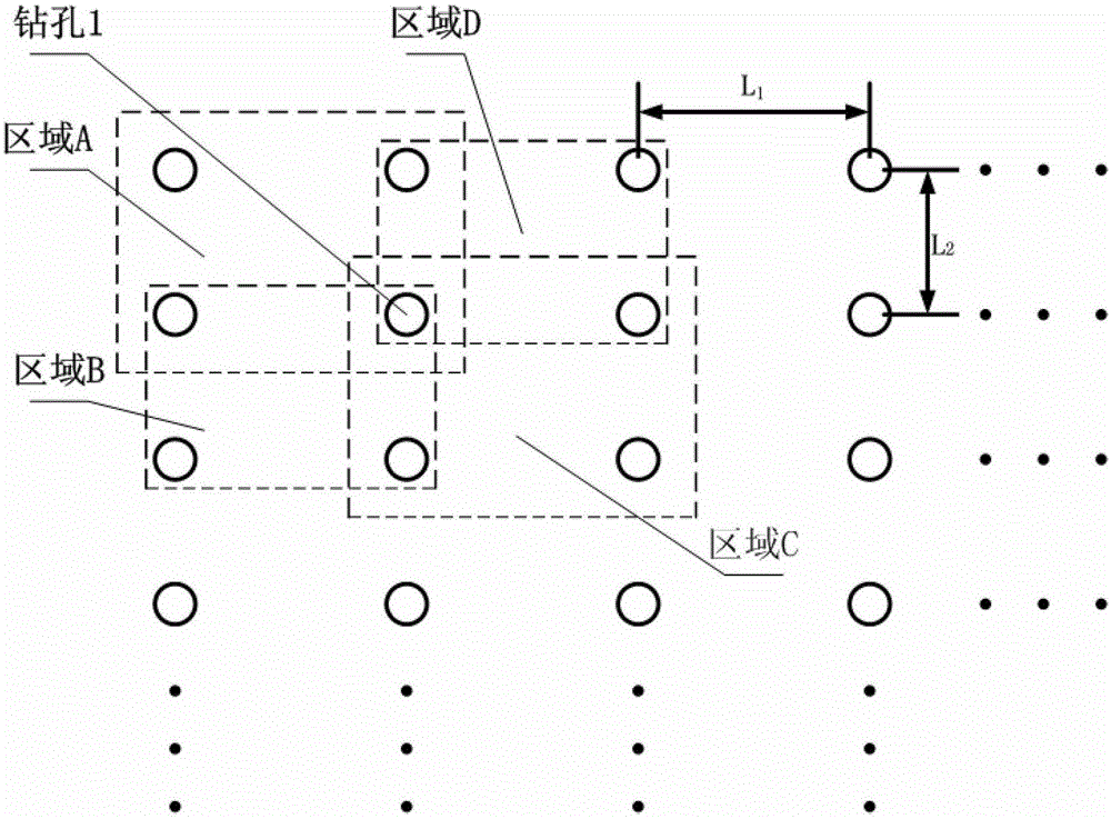
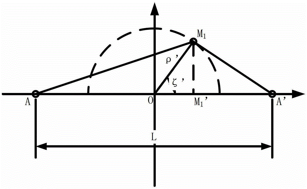
The invention discloses a hole wall representation temperature based simulation design method for drill hole space and belongs to the field of drill hole space design in the geothermal technology. The simulation design method is characterized in that the method comprises arbitrarily selecting four adjacent drill holes with perpendicular U-shaped buried pipes arranged inside from a drill hole group to form a four-drill-hole region, which is also called a unit drill hole group region; dividing the region into two double-drill-hole sub-regions from a horizontal direction, calculating a general formula for a transient temperature of a point M1 under a cylindrical coordinate system of the double-drill-hole sub-regions; mapping the point M1 transversely onto a vertically contacted virtual line heat source or actual line heat source to obtain the hole wall representation temperature Tb1 under the double drill holes; calculating the hole wall representation temperature Tb2 by transverse mapping of middle point M2 in the four-drill-hole region onto the virtual line heat source or the actual line heat source in the same way; setting thresholds of hole wall representation temperature change rates P1 and P2 of the double-drill-hole sub-regions and the four-drill-hole region as P1MAX and P2MAX successively; and calculating L1OPT and L2OPT in a threshold range successively through multiple times of iteration to obtain an optimal value of the drill hole space. According to the simulation design method, contradictions between the drill hole space and the heat exchanging efficiency are solved, the problem of slow calculation speed is solved under the condition that the accuracy is guaranteed, and the drill hole space and the hole wall representation temperature are balanced.

Description

technical field [0001] Ground source heat pump technology is an efficient, energy-saving and environmentally friendly energy utilization method, which can realize the transfer of heat from low-level heat sources to high-level heat sources by consuming a small amount of high-grade energy. In recent years, with the strong support of the Chinese government, the number of ground source heat pump projects has been increasing year by year, but its key technologies and related theories still need to be improved and perfected. [0002] The ground source heat exchanger is the underground heat exchange device of the ground source heat pump system. It usually consists of a set of regularly arranged boreholes and vertical U-shaped buried pipes. The heat exchange efficiency of the ground source heat exchanger directly affects the operating efficiency of the ground source heat pump system, so its size design is an essential link before building the entire system. However, in order to save ...

Claims


Application Information

Patent Timeline
Patent Type & Authority Patents(China)
IPC IPC(8): G06F17/50
Inventor 张亚庭张晔姜伟昌焦全文
Owner BEIJING UNIV OF TECH
Learn More