High-toughness cold-drawn non-heat-treated wire rod, and method for manufacturing same
一种非热处理、高韧性的技术,应用在热处理炉、热处理设备、制造工具等方向,能够解决不适用冷锻等问题,达到优异高韧性的效果
- Summary
- Abstract
- Description
- Claims
- Application Information
AI Technical Summary
Problems solved by technology
Method used
Image
Examples
Embodiment 1)
[0050] Wire rods were produced from billets satisfying the composition as described in Table 1 under the manufacturing conditions described in Table 2. Tensile strength and impact toughness in the fabricated wire rods are listed, and the measurement results are shown in Table 2.
[0051] Table 1
[0052]
[0053] Table 2
[0054]
[0055] It can be seen from the results in Table 2 that the tensile strength of the wire rod of the present invention is in the range of 650 MPa to 750 MPa. This range shows an increase in strength during cold drawing and an optimum range of tensile strength with a continued decrease in toughness after hot rolling.
[0056] Therefore, it was not easy to obtain sufficient strength for Comparative Wire Rods 1 to 3, and it was difficult to obtain sufficient cold drawability for Comparative Wire Rods 4 and 5.
Embodiment 2)
[0058] Meanwhile, when the cooling rate after hot rolling was changed, preferred tensile strength and impact properties were observed. To this end, steel slabs of wire rods 1 and 2 according to the invention were applied in the method of Table 3 to demonstrate tensile strength and impact toughness, the results of which are shown in Table 3. More preferable cooling rate conditions were determined from the results in Table 3.
[0059] table 3
[0060]
[0061] As shown in Table 3, it can be seen that the cooling rate at which the most appropriate tensile strength and impact toughness can be obtained even when the sample is the wire rod of the present invention is in the range of 0.5 to 1.5°C / s. Therefore, it can be confirmed that cooling conditions may be preferable conditions. That is, the wire rods 1-1 and 2-1 of the present invention classified as comparative examples could not obtain appropriate strength, and the wire rods 1-5, 2-4, and 2-5 of the present invention obta...
Embodiment 3)
[0063] In order to determine the effect on strength increase and impact toughness, the inventive wire rod 3 (according to the conditions in Table 1 and Table 2) and the comparative wire rod 6 of Example 1 were prepared.
[0064] The comparative wire rod 6 included 0.25% by weight of C and 0.5% by weight of Mn, and the rest of the conditions were the same as the wire rod 3 of the present invention.
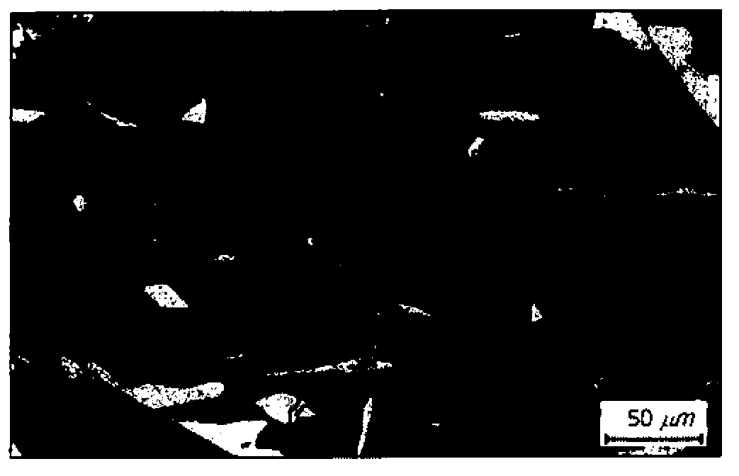
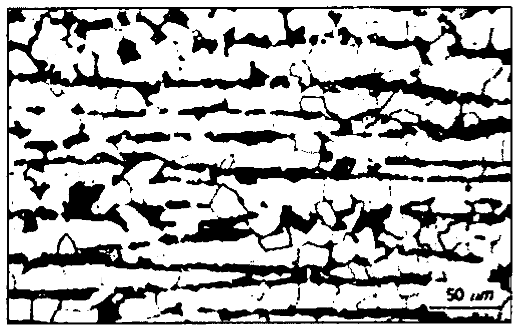
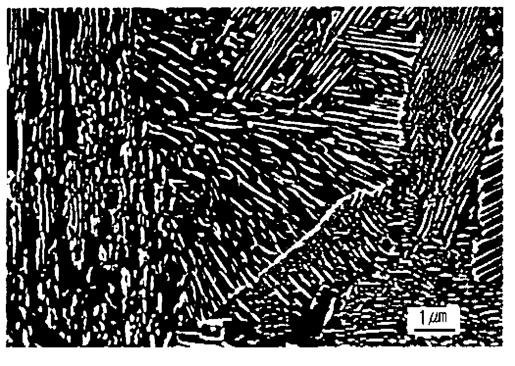
[0065] The microstructures of the wire rod 3 of the present invention and the comparison wire rod 6 were observed and shown in figure 1 and 2 , and their enlarged images are shown in image 3 and 4 .
[0066] figure 1 and image 3 The microstructure of the wire rod 3 of the present invention is shown, where the black parts represent degenerated pearlite and the white parts represent ferrite. It was confirmed that degenerate pearlite accounted for not less than 90% of the area fraction. Also, you can get from image 3 It was determined that ferrite and cementite formed a mix...
PUM
| Property | Measurement | Unit |
|---|---|---|
| tensile strength | aaaaa | aaaaa |
| tensile strength | aaaaa | aaaaa |
| volume | aaaaa | aaaaa |
Abstract
Description
Claims
Application Information
 - R&D
- Intellectual Property
- Life Sciences
- Materials
- Tech Scout
- Unparalleled Data Quality
- Higher Quality Content
- 60% Fewer Hallucinations
Browse by: Latest US Patents, China's latest patents, Technical Efficacy Thesaurus, Application Domain, Technology Topic, Popular Technical Reports.
© 2025 PatSnap. All rights reserved.Legal|Privacy policy|Modern Slavery Act Transparency Statement|Sitemap|About US| Contact US: help@patsnap.com


