
Method for testing ammonia escape of flue gas denitrification system

A technology of ammonia escape and detection method, which is applied in the direction of measuring devices, instruments, scientific instruments, etc., and can solve problems such as uneven distribution of ammonia escape, difficult splicing of heating guns, and sampling loss

Active Publication Date: 2013-07-17
ELECTRIC POWER RES INST OF STATE GRID ZHEJIANG ELECTRIC POWER COMAPNY +1
View PDF0 Cites 9 Cited by
  • Summary
  • Abstract
  • Description
  • Claims
  • Application Information

AI Technical Summary

Problems solved by technology

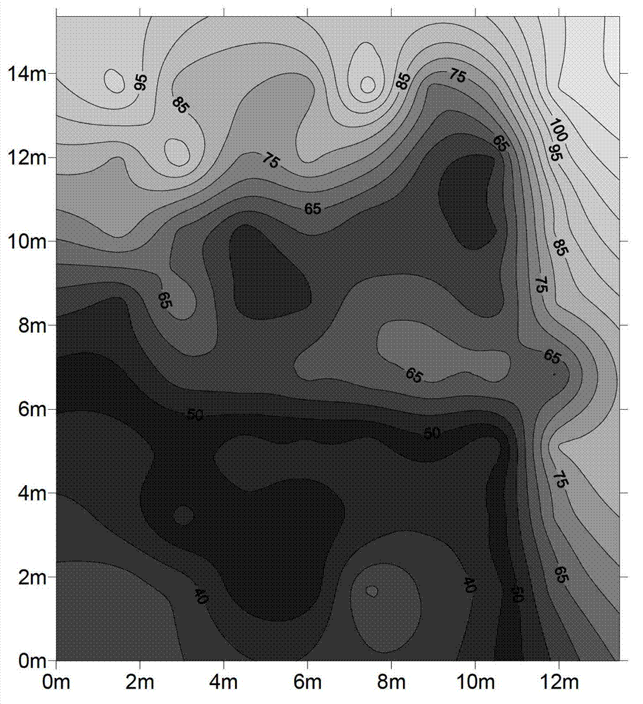
[0007] The study of the present invention shows that when using this test method to test the ammonia escape of the flue gas denitrification system, due to the uneven matching of the injected ammonia and the NOx in the flue gas, the distribution of the ammonia escape at the outlet of the denitrification system is relatively uneven, but because the heating gun It is difficult to splice. For portability and transportation, it can only be made within 2m. However, the cross-section of the outlet flue of the denitrification system is relatively large, generally larger than 5m×5m, so it is impossible to uniformly distribute the test on the entire cross-section of the outlet flue of the denitrification system. resulting in a lack of representativeness of the test results
; and in order to prevent the dust in the flue gas from entering the absorption bottle, it is necessary to install a filter device at the head of the flue gas collection pipe. During the process of extraction and collection, a certain amount of smoke dust will accumulate in the filter device. In the device, ammonia in the flue gas will be adsorbed, resulting in sampling loss, so that the obtained test results cannot reflect the real ammonia escape situation

Method used


Image

  • Method for testing ammonia escape of flue gas denitrification system
  • Method for testing ammonia escape of flue gas denitrification system
  • Method for testing ammonia escape of flue gas denitrification system

Examples


Embodiment 1

[0085] NH to be purchased 4 + The standard solution was diluted and prepared to obtain standard solutions with a mass concentration of 0.2mg / L, 1.0mg / L, 2.0mg / L, 4.0mg / L and 10.0mg / L, and the above series of concentrations of NH 4 + The standard solution was detected by ion chromatography, the inhibition current detected by ion chromatography was 59mA, the quantitative loop volume was 10μL, the separation column was CS12A-4×250mm cation separation column, the elution method was isocratic elution, and the flow rate of the eluent was 1.0mL / min, the column temperature is 30°C, the cell temperature is 35°C, and the column pressure is 1200psi;

[0086] The standard solution of each concentration was detected in parallel 3 times to obtain the corresponding peak areas of the standard solutions of each concentration, and then the concentration-peak area curve was fitted by the least squares method for calibration to obtain the NH 4 + standard curve.

Embodiment 2

[0088] This embodiment detects the escape of ammonia under the condition of working condition 1 of the reactor A of the denitrification system. Using the method in the national standard "Electric Precipitator Performance Test Method" with the standard number GB / T13931-2002, the outlet flue section of the air preheater is uniformly distributed, and the air preheater is tested using a pitot tube and a parallel sampling instrument for smoke and dust. The cross-section of the outlet flue is subjected to isokinetic sampling, the smoke and dust in the flue gas are extracted, and after mixing evenly, the sample to be tested containing solid ammonia is obtained;

[0089] Weigh 1.0000g of the described sample to be tested containing solid ammonia, place it in a beaker, add 10g of deionized water thereto to obtain a solid ammonia sample solution to be tested;

[0090] A hydrochloric acid solution with a mass fraction of 10% is placed in a potentiometric titrator, and then the pH value o...

Embodiment 3

[0098] According to the technical scheme of Example 2, the ammonia escape under the working condition 2 of the reactor A of the denitrification system is detected. The difference is that the mass of the sample to be tested containing solid ammonia in this example is 2.0000 g; the mass of deionized water is 100 g. The pH value of solid ammonia sample solution is between 6.1~6.7; The time of stirring is 1.5 hours, obtains denitrification system ammonia and escapes, and the result is as shown in table 1, and table 1 is embodiment 2~8 of the present invention and comparative example 1~ 7 to get the test results.


PUM


Abstract

The invention provides a method for testing ammonia escape of a flue gas denitrification system. The method includes: collecting flue dust in flue gas of an outlet flue of an air preheater, mixing the flue dust with water, and controlling the water-to-dust ratio and the pH (potential of hydrogen) value of solution to achieve accurate measurement of ammonia content in flue dust; and collecting gas in the outlet flue of the air preheater, detecting to obtain gaseous ammonia content in the gas, and obtaining a detection result of ammonia escape of the flue gas denitrification system according to the solid-state ammonia content in the flue dust and the gaseous ammonia content in the gas. The method detects the gaseous ammonia mixed in the flue gas after ammonia escape, as well as detects the solid-state ammonia absorbed on the flue dust, the water-to-dust ratio is controlled to be (10-100): 1 while the pH value of the solution is controlled to be 6.0-6.8 during solid-state ammonia detection, and accordingly the obtained detection result can show ammonia escape of the flue gas denitrification system more accurately and truly, and further the method is more conducive to directing of production processes.

Description

technical field [0001] The invention relates to the technical field of denitrification systems for coal-fired boilers, in particular to a method for detecting ammonia escape in a flue gas denitrification system. Background technique [0002] With the development of my country's electric power industry, NOx emissions are increasing day by day. As we all know, NOx pollution can form acid rain, photochemical smog, and destroy the ecological environment. Its impact has attracted more and more attention and attention. With the improvement of my country's emission standards, coal-fired generating units basically require the installation of SCR (selective catalytic reduction) flue gas denitrification devices to reduce NOx emissions. [0003] The principle of SCR flue gas denitrification is: under the action of a catalyst, ammonia is injected into the flue gas, and NO x catalytic reduction to N 2 and H 2 O, because it is impossible to achieve 100% uniform mixing of the injected a...

Claims


Application Information

Patent Timeline
Patent Type & Authority Applications(China)
IPC IPC(8): G01N30/02
Inventor 曹志勇金东春钱洲亥吴芳芳周飞梅汤治
Owner ELECTRIC POWER RES INST OF STATE GRID ZHEJIANG ELECTRIC POWER COMAPNY
Learn More