Pneumatic sealing assembly of molding drum transmission box and method thereof

A kind of pneumatic sealing and transmission sealing technology, which is applied in the direction of engine sealing, engine components, other household appliances, etc., can solve the problems of inability to achieve precise sealing, affecting the maneuverability of the main shaft, unstable main shaft air pressure, etc., to improve the accuracy of transmission. The effect of improved performance and drive performance, and easy maintenance and replacement

Inactive Publication Date: 2013-06-26
MESNAC
View PDF5 Cites 3 Cited by
  • Summary
  • Abstract
  • Description
  • Claims
  • Application Information

AI Technical Summary

Problems solved by technology

[0005] The starting point of the above patent application is to improve the service life of the bearing, as well as the accuracy and stability of the main shaft rotation, but the structure only includes the main shaft without setting Inner shaft, so the forming drum can only realize the circumferential rotation; in addition, the rotary valve is set on the main shaft and cannot be sealed precisely, thus causing the air pressure in the main shaft to be unstable, which directly affects the locking of the traveler and the inflation inside the tire blank and other operations; and the pneumatic brake is set on the end of the main shaft, which will also affect the maneuverability of the main shaft when it rotates

Method used


Image

  • Pneumatic sealing assembly of molding drum transmission box and method thereof
  • Pneumatic sealing assembly of molding drum transmission box and method thereof
  • Pneumatic sealing assembly of molding drum transmission box and method thereof

Examples


Embodiment 1

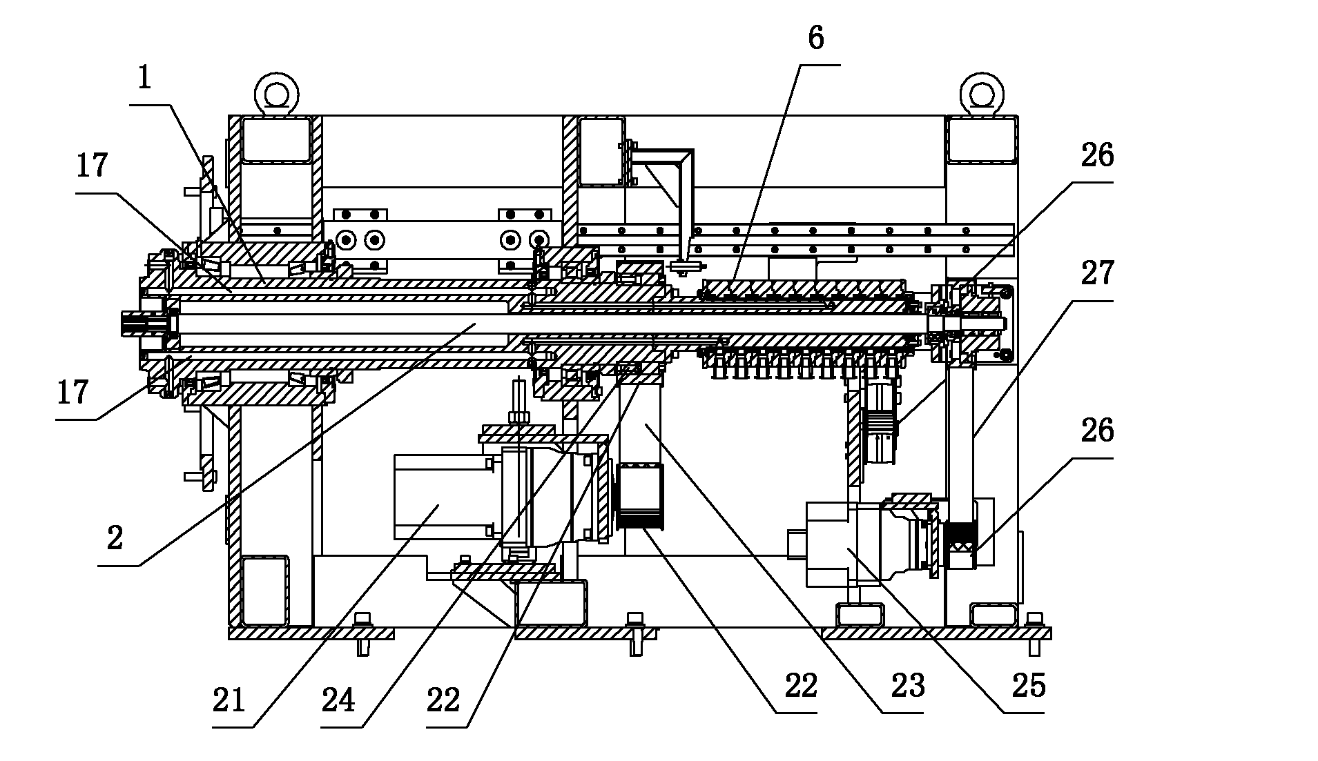
[0043] Example 1, such as figure 1 and figure 2 As shown, the pneumatic sealing assembly of the forming drum transmission box is arranged inside the transmission box 3, the outer end of the pneumatic sealing assembly 6 is connected to the main shaft 1, and the main shaft air passage 17 inside the main shaft 1 is connected to the air passage inside the pneumatic sealing assembly 6. Pass;

[0044] The pneumatic seal assembly 6 is sheathed on the outer diameter of the inner shaft 2 , and the radial connection between the inner end of the pneumatic seal assembly 6 and the radial direction of the inner shaft 2 is carried out through a rolling bearing 7 and sealed.

[0045] Wherein, the inner shaft 2 carrying the forming drum lock block is sleeved on the inner diameter of the main shaft 1;

[0046] Inside the transmission box 3, a main shaft driving device 4 for driving the main shaft 1 to rotate in a circumferential direction and an inner shaft driving device 5 for driving the i...


PUM


Abstract

The invention provides a pneumatic sealing assembly of a molding drum transmission box and a method thereof. A transmission sealing device which is in butt joint with a main shaft is adopted so that the combination of pneumatic transmission and sealing treatment is realized when the main shaft rotates so that the whole air tightness of a transmission part is improved and the stability of air pressure in the main shaft is guaranteed. The pneumatic sealing method of a molding drum comprises the following steps that: an inner shaft for bearing a molding drum locking block is sleeved with the inner diameter of the main shaft; a main shaft driving device for driving the main shaft to do peripheral rotation and an inner shaft driving device for driving the inner shaft to do the peripheral rotation are respectively arranged inside a transmission box; the main shaft is in butt joint with the outer side end of the pneumatic sealing assembly and the main shaft is communicated with an air path in the pneumatic sealing assembly; the pneumatic sealing assembly is sleeved on the outer diameter of the inner shaft; the inner side end of the pneumatic sealing assembly and the radial direction of the inner shaft are connected through a rolling bearing and are subjected to sealing treatment; and therefore, when the main shaft and the inner shaft respectively do the peripheral rotation, compressed air is introduced into an air path in the main shaft through the pneumatic sealing assembly.

Description

technical field [0001] The invention relates to a pneumatic sealing assembly of a forming drum transmission box used in the preparation of rubber tires and a transmission sealing method thereof, belonging to the field of rubber machinery. Background technique [0002] Based on the existing rubber tire preparation process, the forming machine usually needs to be separately equipped with a forming drum for completing tire blank processing, so as to transport the prepared carcass assembly and belt layer-tread assembly to the forming drum, so as to complete the overall process manufacturing cycle. [0003] In order to complete the turn-up process, the forming drum needs to be rotated in the circumferential direction to fit the film layer, and the tiles on the surface of the drum are radially expanded and contracted to lock the traveler and inflate the tire inside, realizing the series of forming drums. The driving mechanism of the action is the forming drum transmission box. ...

Claims


Application Information

Patent Timeline
Patent Type & Authority Applications(China)
IPC IPC(8): B29D30/26F16J15/40B29L30/00
CPCB29D30/26
Inventor 王延书杨慧丽王永琴奚道双马慧
Owner MESNAC
Why Eureka
Try Eureka