Selective doping method for solar cell based on reverse diffusion

A solar cell and reverse diffusion technology, applied in circuits, photovoltaic power generation, electrical components, etc., can solve problems such as reducing battery efficiency, reducing production efficiency, and increasing costs, reducing the steps to remove amorphous silicon films and improving production efficiency. , to ensure the effect of heavy doping

Inactive Publication Date: 2013-06-19
NANTONG UNIVERSITY
View PDF5 Cites 3 Cited by
  • Summary
  • Abstract
  • Description
  • Claims
  • Application Information

AI Technical Summary

Problems solved by technology

Among them, the two-step diffusion method is to firstly diffuse the top electrode area, and then lightly diffuse the entire emission area. Control; the screen phosphate slurry method is to use a screen to print a high-concentration phosphate slurry locally. Through its diffusion and volatilization, one diffusion can make the top electrode area form a heavy doping, and other areas form a light doping. However, due to the use of local Phosphorus slurry as a diffusion source will inevitably lead to uneven surface diffusion, which will reduce the efficiency of the battery
The diffusion mask method is to lightly dope first, then perform laser or photolithography masking, and then carry out secondary heavy doping on the top electrode area. This method reduces the selectivity of the top electrode area due to light doping first. The difference between the impurity concentration of the substrate and the substrate during doping can better control the selective doping area of ​​the battery, but laser or photolithography methods are required, which increases the cost and reduces the production efficiency
[0004] In summary, there are certain defects in the current main selective doping methods. Therefore, it is necessary to find a new type of selective doping solar cell production process.

Method used


Image

  • Selective doping method for solar cell based on reverse diffusion
  • Selective doping method for solar cell based on reverse diffusion
  • Selective doping method for solar cell based on reverse diffusion

Examples


Embodiment 1

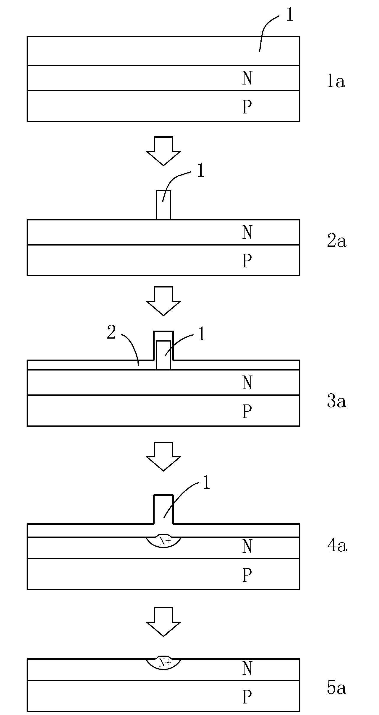
[0034] Such as figure 1 Shown is a schematic flow chart of the method for selective doping of solar cells based on reverse diffusion in the present invention, which specifically includes the following steps:

[0035] 1a. Place the P-type monocrystalline silicon wafer in a humid oxygen environment for high-temperature pre-diffusion, so that phosphorus element diffuses into the silicon wafer to form a PN junction. At the same time, a phosphosilicate glass layer 1 with a thickness of about 0.05 microns is formed on the silicon wafer surface. The concentration of phosphorus in the glass layer 1 is about 1e19 / cm 3 ;The process temperature of high temperature pre-diffusion is 1000°C, and the duration is 30 minutes;

[0036] 2a. Retain the phosphosilicate glass in the top electrode area by screen printing, and remove the phosphosilicate glass in other areas on the silicon wafer with hydrofluoric acid buffer;

[0037] 3a. Depositing an intrinsic amorphous silicon layer 2 with a thic...

Embodiment 2

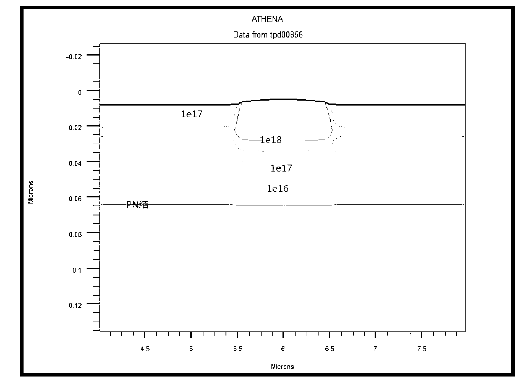
[0042] The steps of this example are the same as those of Example 1, the difference lies in the process parameters of high-temperature diffusion in dry oxygen environment in step 4a (the fourth step). In this example, the process temperature of high-temperature diffusion is 1000°C, and the duration is 5 minutes . After using the simulation software to simulate the second method of this embodiment, the impurities in the silicon wafer can be seen image 3 . The curves in the simulation result graph respectively represent the concentration of the doping element (phosphorus) and the position of the PN junction.

Embodiment 3

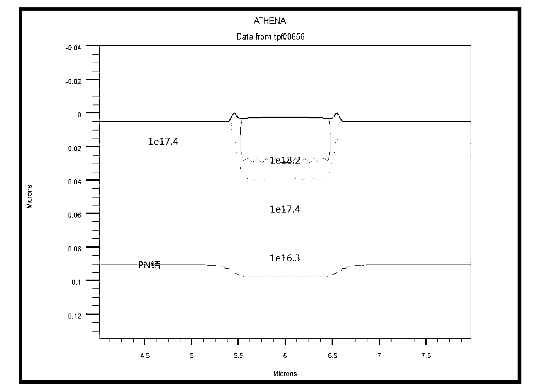
[0044] The steps of this example are the same as those of Example 1, the difference lies in the process parameters of high-temperature diffusion in dry oxygen environment in step 4a (the fourth step). In this example, the process temperature of high-temperature diffusion is 1100°C, and the duration is 2 minutes . After using the simulation software to simulate the third method of this embodiment, the impurities in the silicon wafer can be seen Figure 4 . The curves in the simulation result graph respectively represent the concentration of the doping element (phosphorus) and the position of the PN junction.

[0045]Comparing the three embodiments of the present invention, it can be seen from the simulation results that the PN junction of the battery is continuously deepened with the increase of the high-temperature diffusion temperature of the reverse diffusion process. The impurity concentration on the surface of the battery first increases and then decreases, but the impur...


PUM


Abstract

The invention relates to a selective doping method for a solar cell based on reverse diffusion. The method includes the steps: diffusing a silicon slice in an aerobic environment at a high temperature to form a PN junction and oxidizing the upper surface of the silicon slice; removing an oxidation layer outside a top electrode area of the silicon slice; depositing an intrinsic amorphous silicon layer on the upper surface of the silicon slice; diffusing the silicon slice in a wet-oxygen environment at a high temperature, reversely diffusing doping elements in a non-top electrode area into the amorphous silicon layer, diffusing doping elements in an oxidation layer of the top electrode area to the top electrode area and oxidizing the amorphous silicon layer and the non-top electrode area of the surface of the silicon slice to form an oxidation layer; and removing the oxidation layer on the surface of the silicon slice to selectively dope the solar cell based on reverse diffusion. By means of reverse diffusion, impurities in the non-top electrode area are absorbed by amorphous silicon, the doping concentration of the non-top electrode area is reduced, the top electrode area is secondarily doped, the doping concentration difference between the top electrode area and the non-top electrode area is further increased, and selective doping effects are improved.

Description

technical field [0001] The invention relates to a method for selective doping of solar cells based on reverse diffusion, and belongs to the technical field of solar cell manufacturing. Background technique [0002] With the improvement of people's awareness of environmental protection, the demand for clean energy is increasing. Among the new clean energy researched by people, solar energy, as a clean energy that is not subject to geographical restrictions, has become the main direction of new energy development in the future. Solar cells are the main devices that people use the sun's light energy to convert into electrical energy. However, the conversion efficiency of solar cells cannot meet people's requirements at present. Improving the conversion efficiency of solar cells and reducing the manufacturing cost of solar cells has become a research hotspot. [0003] Selectively doped solar cells are an effective low-cost and high-efficiency solar cell. The structural featu...

Claims


Application Information

Patent Timeline
Patent Type & Authority Applications(China)
IPC IPC(8): H01L31/18
CPCH01L21/225H01L31/1804Y02E10/547Y02P70/50
Inventor 花国然王强朱海峰姚滢张华
Owner NANTONG UNIVERSITY
Why Eureka
Try Eureka