
A method of fabricating a planar thermopile for a calorimeter

A manufacturing method and thermopile technology, applied in the manufacture/processing of thermoelectric devices, etc., can solve problems such as poor placement uniformity of thermocouples, difficulty in processing planar thermopile, and difficulty in ensuring temperature measurement sensitivity, etc., to reduce relative error and small size , the effect of high practical value

Inactive Publication Date: 2015-08-19
中国航天科工集团第二研究院二〇三所
View PDF6 Cites 0 Cited by
  • Summary
  • Abstract
  • Description
  • Claims
  • Application Information

AI Technical Summary

Problems solved by technology

[0003] The purpose of the present invention is to provide a method for manufacturing a planar thermopile used in calorimeters, which solves the problems of difficult processing of planar thermopile, poor placement uniformity of thermocouples, small number of thermocouples, and difficulty in ensuring temperature measurement sensitivity.

Method used


Image

  • A method of fabricating a planar thermopile for a calorimeter
  • A method of fabricating a planar thermopile for a calorimeter
  • A method of fabricating a planar thermopile for a calorimeter

Examples


Embodiment Construction

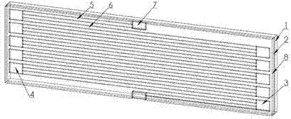
[0027] The specific steps of a method for manufacturing a planar thermopile for a calorimeter are:

[0028] The first step is to make a metal photolithography mask

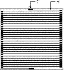
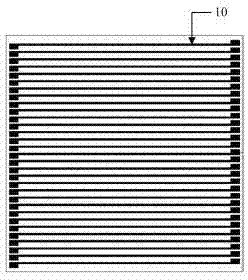
[0029] Make the mask plate required for the photolithography of nickel metal 9 and platinum metal 10, expose the patterns of nickel metal 9 and platinum metal 10 on the chromium plate at a working temperature of 1600K, and expose the patterns of nickel metal 9 and platinum metal 10 one by one Elemental exposure, making a mask pattern with a magnification of 1:5.

[0030] The second step is to process the mask for dry etching and pad lithography

[0031] Make the mask plate required for dry etching and pad 7 thickening, and use electron beam exposure technology to expose the pattern elements of pad 7 one by one at a working temperature of 1600K on the chromium plate for dry etching and pad 7, Make a mask pattern with 1:5 magnification.

[0032] The third step is to grow the insulating layer

[0033] On the subs...


PUM


Abstract

The invention discloses a method for producing a planar thermopile for thermometers capable of rapidly measuring the distribution of the surface temperature difference between two objects placed on the same level. The method has the following four characteristics: the thermopile is a replaceable element, the number of thermocouples forming the thermopile can be conveniently changed by adjusting the processing technique, a produced thermopile temperature sensor has 200 sets of thermocouples in the area of 85mm multiplied by 50mm, and according to need, the number of the thermocouples can be increased by reducing the line width and the distance between lines. The time constant of the thermopile is low, and transient temperature difference can be measured. The surface area of the thermopile can be changed according to requirement in order to be adapted to temperature difference measurement at different distances. The structure of the thermopile is compact and simple, and the thermopile is convenient to mount, and can be used for measuring little heat.

Description

technical field [0001] The invention relates to a method for manufacturing a planar thermopile, in particular to a method for manufacturing a planar thermopile for a calorimeter. Background technique [0002] Usually, most of the manufacturing methods of thermopile adopt welding process or coating technology. There is a big gap in terms of tightness and so on. There are two options for the coating process, ion sputtering or photolithography coating. The advantage of the ion sputtering process is that it can be repeatedly coated with a set of templates. The disadvantage is that it is difficult to clamp, and the process level is low, and there is little room for miniaturization. Contents of the invention [0003] The purpose of the present invention is to provide a method for manufacturing a planar thermopile used in calorimeters, which solves the problems of difficult processing of planar thermopile, poor placement uniformity of thermocouples, small number of thermocouple...

Claims


Application Information

Patent Timeline
Patent Type & Authority Patents(China)
IPC IPC(8): H01L35/34H10N10/01
Inventor 何巍张伟伟程春悦
Owner 中国航天科工集团第二研究院二〇三所
Learn More